
Camaro V6-3.8L VIN K (1995)
6. Nuts (101).
7. Mirror assembly (109).
INSTALL OR CONNECT
1. Mirror assembly (109).
2. Tighten nuts (101) to 6 Nm(53 lb. in.).
3. Electrical connector, if equipped.
^
Connect electrical connector.
^
Push rosebud clip on electrical connector into hole in mirror assembly (109).
4. Front side door trim assembly, if removed.
5. Remote handle to bezel assembly (84), if equipped.
^
Align slot in remote handle to tab on bezel assembly (84).
^
Push remote handle into bezel assembly (84) to engage threads on remote handle onto metal clip in bezel assembly (84).
6. Bezel assembly (84).
^
Align retainers in bezel assembly (84) to holes in applique assembly.
7. Tighten bolt/screw (85) to 4 Nm (35 lb. in.).
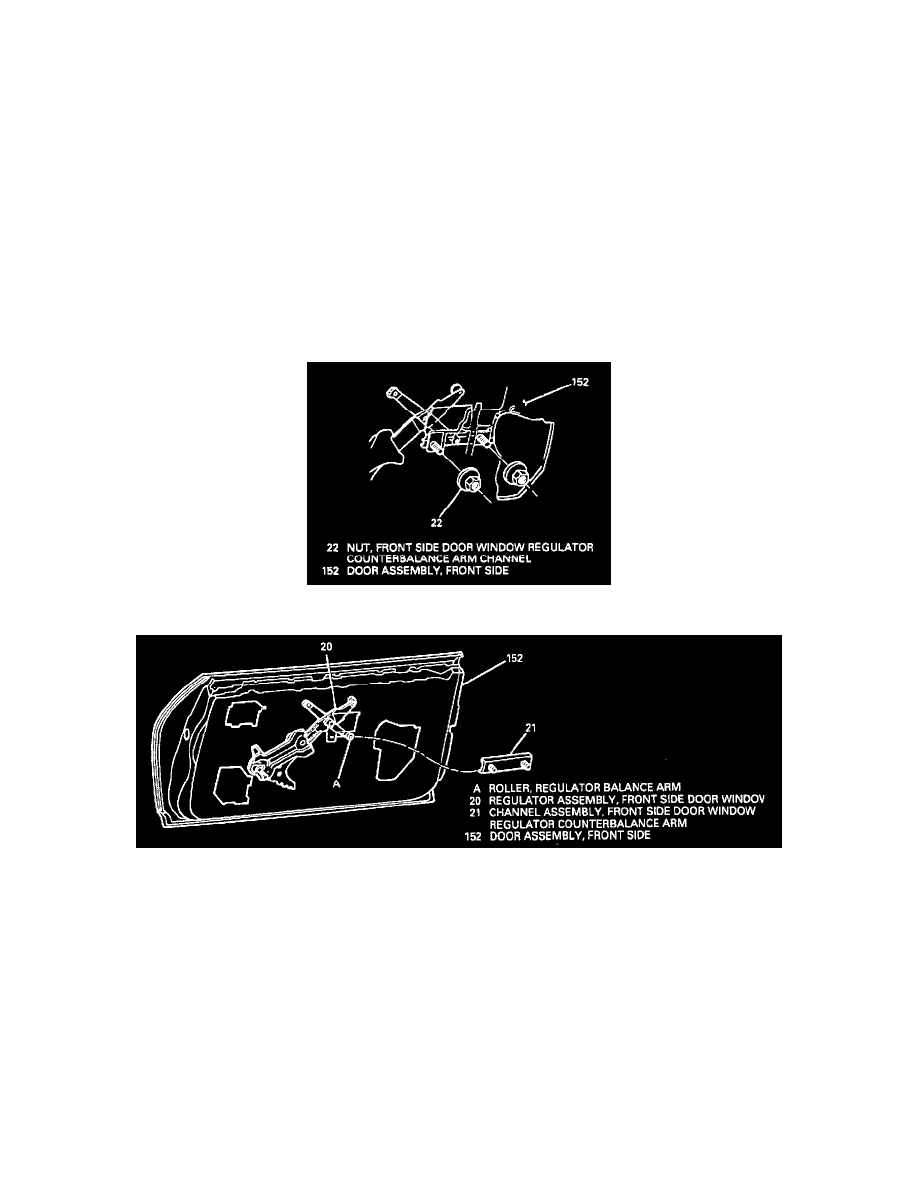
Door Window Regulator Counterbalance Arm Channel Assy.
Removing Front Side Door Window Regulator Counterbalance Arm Channel Nuts (Typical)
Removing Front Side Door Window Regulator Counterbalance Arm Channel Assembly (Typical)
REMOVE OR DISCONNECT
1. Raise window.
2. Front side door trim assembly.
3. Front side door water deflector as needed.
4. Nuts (22) attaching channel assembly (21) to door inner panel.
5. Channel assembly (21) from window regulator balance arm roller.
6. Channel assembly (21) through access hole.
INSTALL OR CONNECT
1. Channel assembly (21) through access hole to window regulator balance arm roller.
2. Channel assembly (21) to door inner panel.
3. Tighten nuts (22) to 10 Nm (89 lb. in.).
4. Front side door water deflector.
5. Front side door trim assembly.