
Camaro V8-5.7L VIN G (1998)
Brake Rotor/Disc: Testing and Inspection
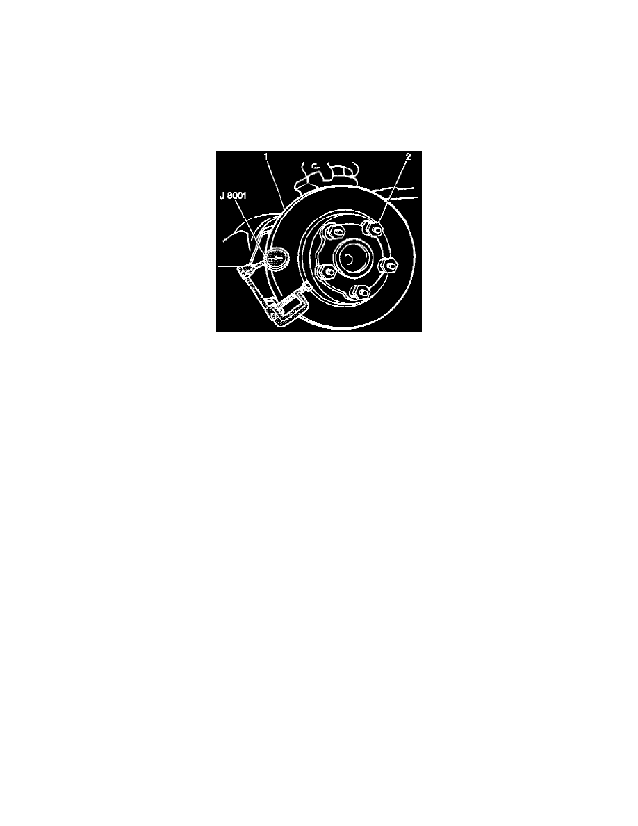
Brake Rotor Lateral Runout Check
REMOVAL PROCEDURE
^
Tools Required
-
J 8001 Dial Indicator Set
Notice: Any time the brake rotor is separated from the wheel bearing flange, clean any rust or foreign material from the mating surfaces of the
wheel bearing flange and the rotor. Failure to do so can result in increased lateral runout of the rotor and brake pulsation.
1. Clean the rotor surface (1).
NOTICE: Always use the correct fastener in the proper location. When you replace a fastener, use ONLY the exact part number for that
application. The manufacturer will call out those fasteners that require a replacement after removal. The manufacturer will also call out the
fasteners that require thread lockers or thread sealant. UNLESS OTHERWISE SPECIFIED, do not use supplemental coatings (paints, greases, or
other corrosion inhibitors) on threaded fasteners or fastener joint interfaces. Generally, such coatings adversely affect the fastener torque and joint
clamping force, and may damage the fastener. When you install fasteners, use the correct tightening sequence and specifications. Following these
instructions can help you avoid damage to parts and systems.
2. Reinstall the wheel nuts (2) in order to retain the rotor.
Tighten the wheel nuts in a star pattern to 140 Nm (100 ft. lbs.).
3. Fasten the J 8001 to the steering knuckle for front or the rear brake mounting flange on the rear axle for rear so that the indicator button contacts
the rotor surface about 13 mm (0.5 inch) from the rotor edge.
4. Set the J 18001 to zero.
5. Turn the rotor one complete revolution. Inspect the runout indicated on the dial. If the TIR exceeds 0.15 mm (0.006 inch), refinish or replace the
rotor.
In some cases, excessive lateral runout of the rotor may be improved by indexing the rotor on the hub, one or two bolt positions from the original
position. Indexing the rotor requires removal and installation of the front brake caliper. For removal of the front brake rotor, refer to Brake Rotor
Replacement (Front). For rear brake roto replacements, refer to Brake Rotor Replacement (Rear).
If the lateral runout cannot be corrected by indexing the front rotor, inspect the hub and the front wheel bearing for excessive lateral runout or
looseness. If the hub lateral runout exceeds 0.040 mm (0.015 inch), replace the hub and bearing. If lateral runout of the hub and bearing is within
specifications, refinish or replace the rotor as necessary.
If the lateral runout cannot be corrected by indexing the rear rotor, inspect thereat axle shaft flange for excessive lateral runout. If the axle flange
lateral runout exceeds 0.040 mm (0.015 inch), replace the axle shaft. If lateral runout of the axle flange hub is within specifications, refinish or
replace the rotor as necessary.