
Camaro V8-5.7L VIN G (1998)
Engine Control Module: Description and Operation
General System Description
PCM
DESCRIPTION
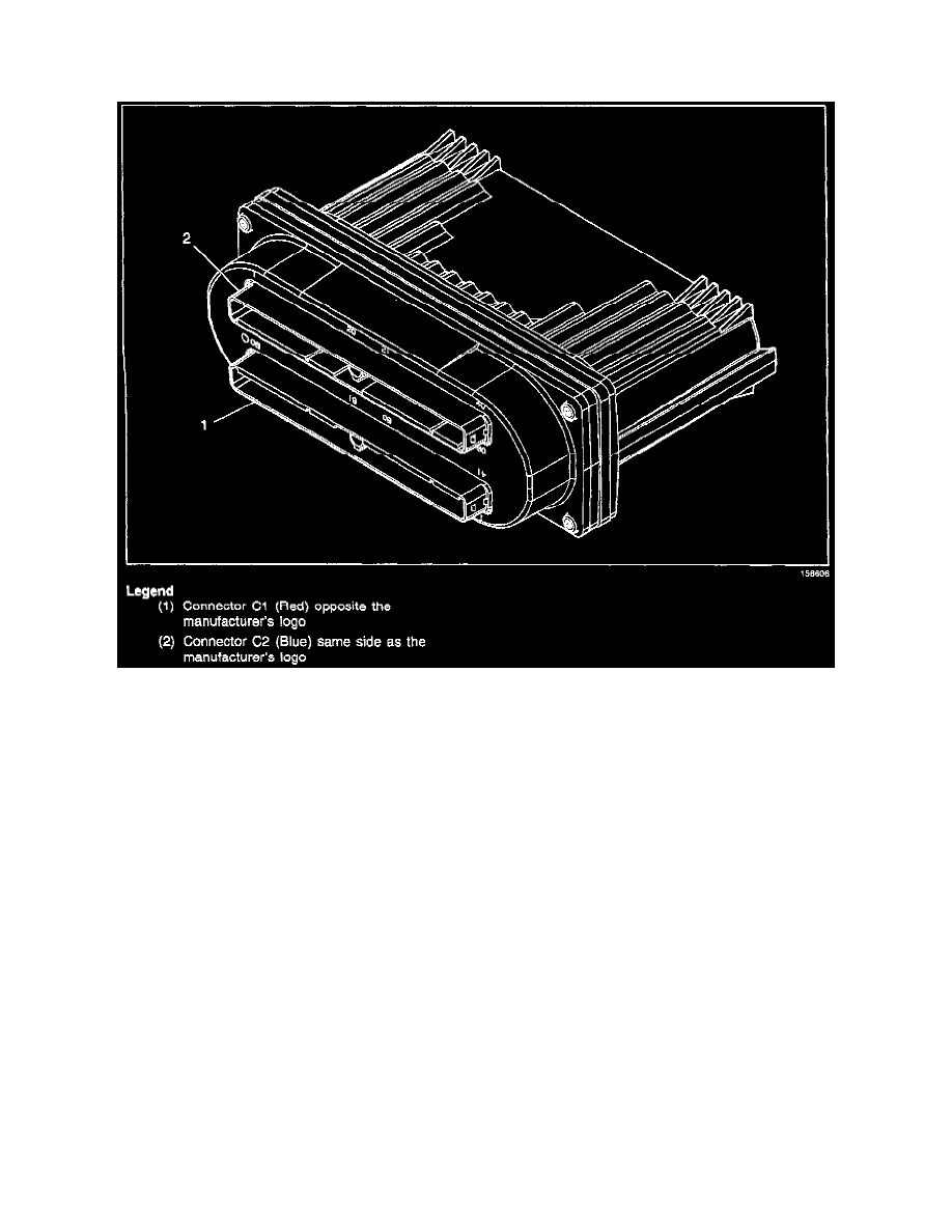
The Powertrain Control Module (PCM) is located in the engine compartment. The PCM is the control center of the vehicle. It controls the
following:
^
Fuel metering system.
^
Transmission shifting.
^
Ignition timing.
^
On-board diagnostics for powertrain functions.
OPERATION
The PCM constantly monitors the information from various sensors, and controls the systems that affect vehicle performance. The PCM also
performs the diagnostic function of the system. It can recognize operational problems. The PCM also alerts the driver through the MIL
(Malfunction Indicator Lamp). When the PCM detects a malfunction, it stores a diagnostic trouble code (DTC). A DTC stored, will identify the
problem areas. This will aid the technician in making repairs.
The PCM supplies either 5.0 or 12.0 volts to power various sensors or switches. This is done through resistances in the PCM. The resistance is so
high in value that a test lamp will not illuminate when connected to the circuit. In some cases, even an ordinary shop voltmeter will not give an
accurate reading because its resistance is too low. Therefore, a digital voltmeter (J 39200) with at least 10 megaohms input impedance is required
to ensure accurate voltage readings.
The PCM controls output circuits such as the injectors, IAC, cooling fan relays, etc. by controlling the ground or the power feed circuit through
transistors or a device called an Output Driver Module.
USE OF CIRCUIT TESTING TOOLS
Do not use a test lamp in order to diagnose the Powertrain electrical systems unless specifically instructed by the diagnostic procedures. Use the
Connector Test Adapter Kit, J 35616 whenever diagnostic procedures call for probing any connectors.