
Camaro V8-5.7L VIN G (1998)
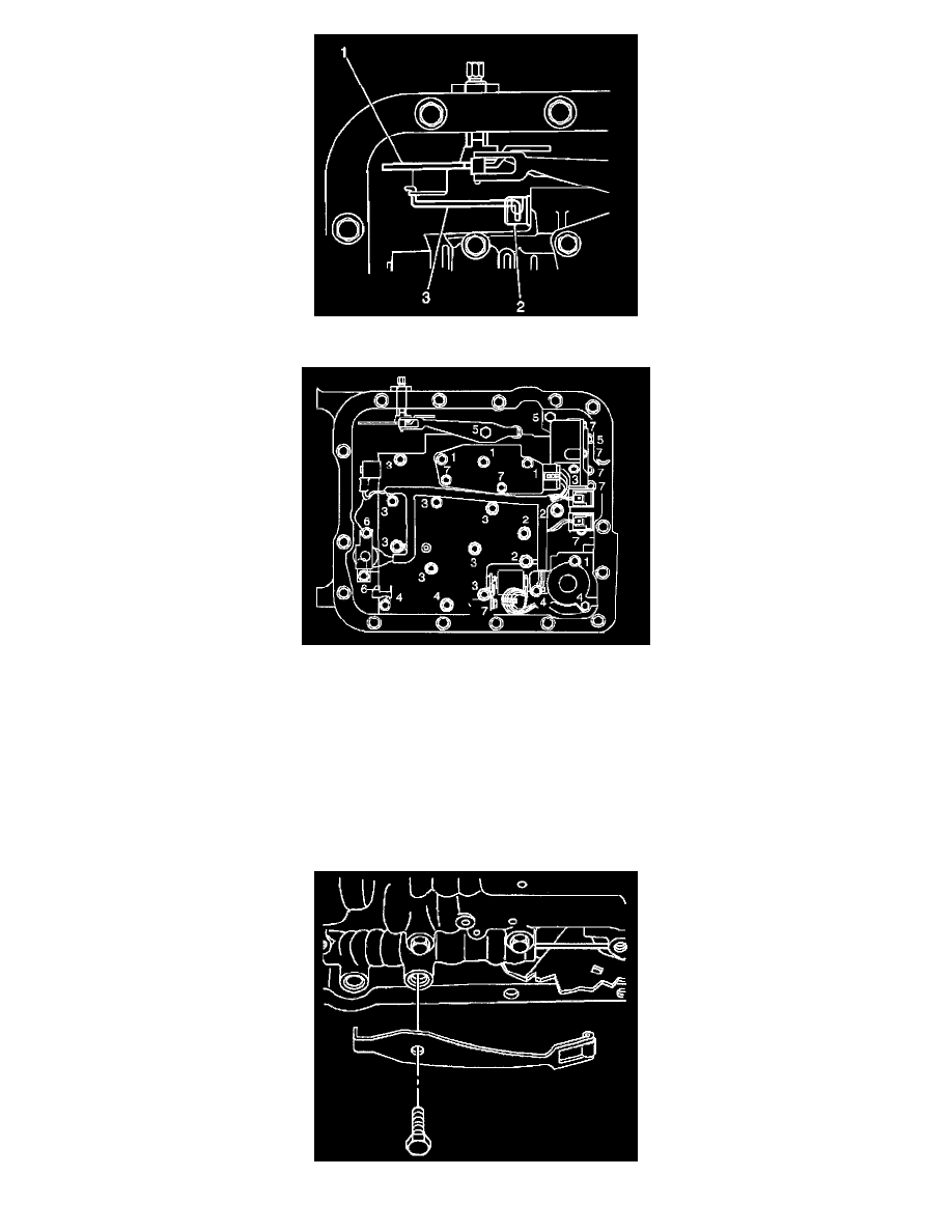
2. Verify that the manual valve link (3) is installed properly to the inside detent lever (1) and the manual valve (2).
3. Install but do not tighten the control valve body bolts which retain only the valve body directly.
Each numbered bolt location corresponds to a specific bolt size and length, as indicated by the following:
^
M6 X 1.0 X 65.0 (1)
^
M6 X 1.0 X 54.4 (2)
^
M6 X 1.0 X 47.5 (3)
^
M6 X 1.0 X 35.0 (4)
^
M6 X 1.0 X 20.0 (5)
^
M6 X 1.0 X 12.0 (6)
^
M6 X 1.0 X 18.0 (7)
IMPORTANT: When installing bolts throughout this procedure, be sure to use the correct size bolt and length in the correct location as specified.