
Camaro V8-6.2L (2010)
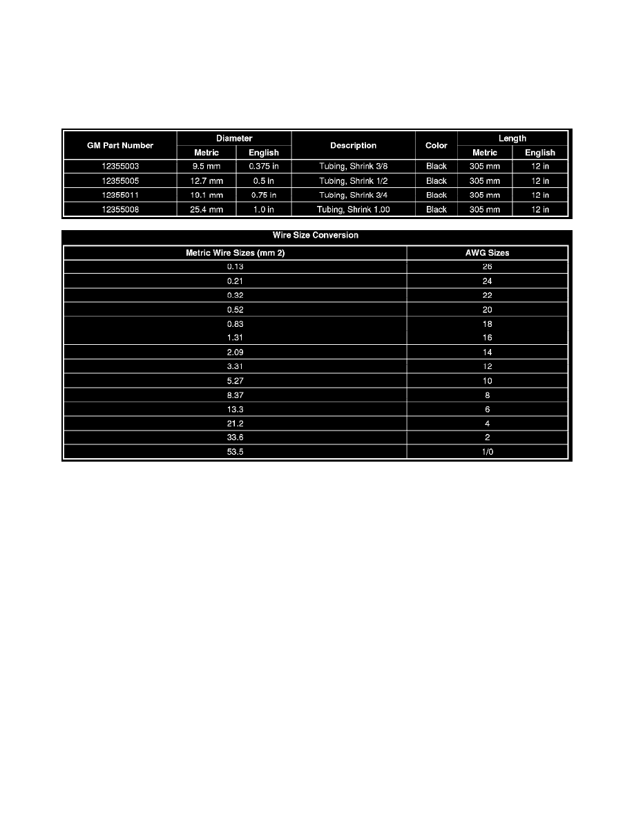
of insulation that needs to be repaired. If the repair is less than 280 mm (11 in), cut the wire within the damaged area. Then slide the appropriate heat
shrink tubing (listed below) over the wire, and repair the wire by splicing the wires together. Refer to Splicing Copper Wire Using Splice Sleeves (See:
Testing and Inspection/Component Tests and General Diagnostics/General Electrical Diagnostic Procedures/Wiring Repairs/Splicing Copper Wire
Using Splice Sleeves). Once the wire is spliced together slide heat shrink tubing over the damaged area and apply heat to seal the repaired wire.
If the wire is damaged, or the damaged area is larger than 280 mm (11 in), then replace the damaged wire by splicing in a new section of wire. Refer to
Splicing Copper Wire Using Splice Sleeves (See: Testing and Inspection/Component Tests and General Diagnostics/General Electrical Diagnostic
Procedures/Wiring Repairs/Splicing Copper Wire Using Splice Sleeves).
SIR/SRS Wiring Repairs
SIR/SRS Wiring Repairs
Special Tools
*
EL-38125-10 - Splice Sleeve Crimping Tool
*
J 38125-5 - Ultra Torch
*
DuraSeal splice sleeves, in order to repair the SIR/SRS wiring
For equivalent regional tools, refer to Special Tools (See: Power and Ground Distribution/Tools and Equipment).
The DuraSeal splice sleeves have the following 2 critical features:
*
A special heat shrink sleeve environmentally seals the splice. The heat shrink sleeve contains a sealing adhesive inside.
*
A cross hatched (knurled) core crimp provides the necessary low resistance contact integrity for these sensitive, low energy circuits.
The Supplemental Inflatable Restraint (SIR) System/Supplemental Restraint System (SRS) requires special wiring repair procedures due to the sensitive
nature of the circuitry. Follow the specific procedures and instructions when working with the SIR/SRS, and the wiring components, such as connectors
and terminals.
SIR/SRS Connector Repair (Plastic Body and Terminal Metal Pin)
Note: Do not use the terminals in the kit in order to replace damaged SIR/SRS system terminals. Use either an SIR/SRS pigtail or a terminated lead
from the SIR Repair Kit Tray.
The terminals in the SIR/SRS system are made with a special plating. This plating provides the necessary contact integrity for the sensitive, low energy
circuits.