
Camaro V8-6.2L (2010)
Note: If the diode is located next to a connector terminal remove the terminal(s) from the connector to prevent damage from the soldering tool.
5. Carefully strip away a section of insulation next to the old soldered portion of the wire(s). Do not remove any more than is needed to attach the
new diode.
6. Check current flow direction of the new diode, being sure to install the diode with correct bias. Reference the appropriate service manual wiring
schematic to obtain the correct diode installation position.
7. Attach the new diode to the wire(s) using 60/40 rosin core solder. Before soldering attach some heat sinks (aluminum alligator clips) across the
diode wire ends to protect the diode from excessive heat. Follow the manufacturer's instruction for the soldering equipment.
8. Reinstall terminal(s) into the connector body if previously removed.
Note: To prevent shorts to ground and water intrusion, completely cover all exposed wire and diode attachment points with tape.
9. Tape the diode to the harness or connector using electrical tape.
Splicing Twisted or Shielded Cable
Splicing Twisted or Shielded Cable
Twisted/shielded cable is used in order to protect wiring from electrical noise. Two-conductor cable of this construction is used between the radio and
the Delco-Bose(R) speaker/amplifier units and other applications where low level, sensitive signals must be carried. Follow the instructions below in
order to repair the twisted/shielded cable.
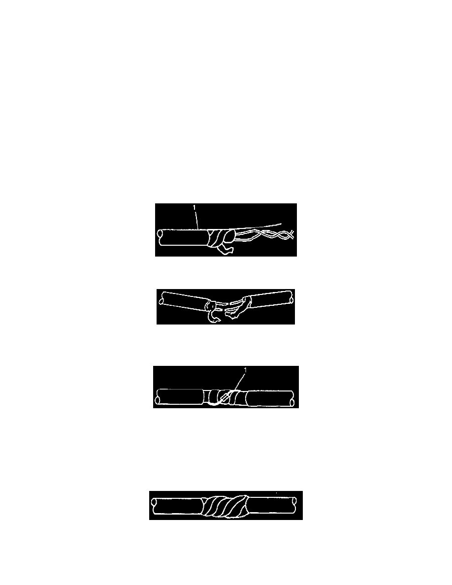
1. Remove the outer jacket (1). Use care not to cut into the drain wire of the mylar tape.
2. Unwrap the tape. Do not remove the tape. Use the tape in order to rewrap the twisted conductors after the splice is made.
3. Prepare the splice. Untwist the conductors and follow the instructions for Splicing Copper Wire Using Splice Sleeves (See: Testing and
Inspection/Component Tests and General Diagnostics/General Electrical Diagnostic Procedures/Wiring Repairs/Splicing Copper Wire Using
Splice Sleeves). Staggering the splices by 65 mm (2.5 in) is recommended.
Note: Apply the mylar tape with the aluminum side inward. This ensures good electrical contact with the drain wire.
4. Re-assemble the cable.
*
Rewrap the conductors with the mylar tape. If the mylar tape is damaged, use 3M product AL-36FR to replace the damaged mylar tape.
*
Use caution not to wrap the drain wire in the tape (1).
*
Follow the splicing instructions for copper wire and splice the drain wire.
*
Wrap the drain wire around the conductors and tape with electrical tape to replace the outer insulation.
5. Tape over the entire cable. Use a winding motion when you apply the tape.
Wiring Repairs