
Camaro V8-6.2L (2010)
Shift Interlock: Testing and Inspection
Transmission Control Lever Malfunction
Transmission Control Lever Malfunction
Diagnostic Instructions
*
Perform the Diagnostic System Check - Vehicle (See: Testing and Inspection/Initial Inspection and Diagnostic Overview/Diagnostic System
Check - Vehicle) prior to using this diagnostic procedure.
*
Review Strategy Based Diagnosis (See: Testing and Inspection/Initial Inspection and Diagnostic Overview/Strategy Based Diagnosis) for an
overview of the diagnostic approach.
*
Diagnostic Procedure Instructions (See: Testing and Inspection/Initial Inspection and Diagnostic Overview/Diagnostic Procedure Instructions)
provides an overview of each diagnostic category.
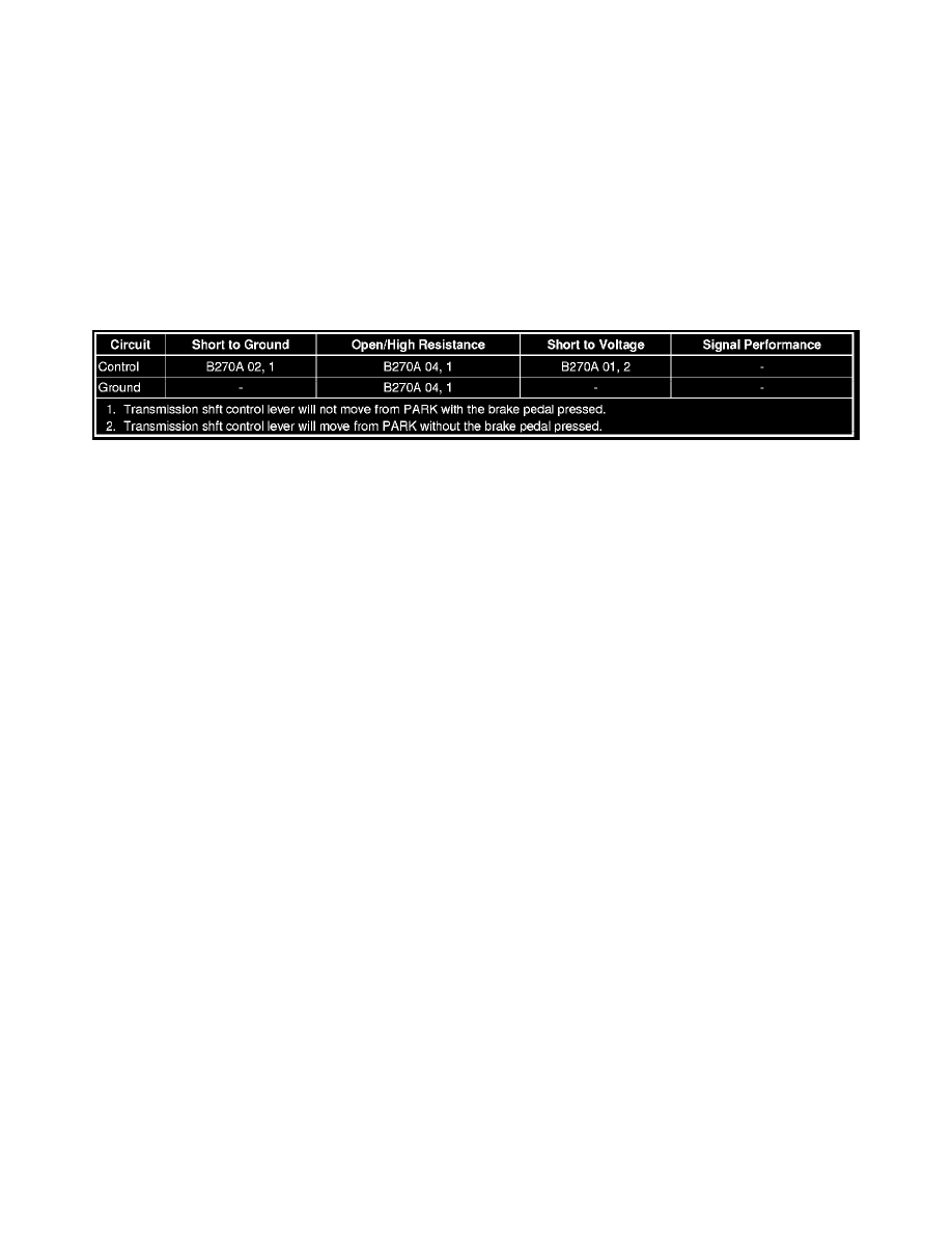
Diagnostic Fault Information
Circuit/System Description
The body control module controls the automatic transmission park lock control solenoid by providing a battery positive voltage to the solenoid. The
body control module controls the voltage supply circuit to the automatic transmission park lock control solenoid. The BCM monitors the voltage and
current flow of the control circuit.
Reference Information
Schematic Reference
Shift Lock Control Schematics (See: Diagrams/Electrical Diagrams)
Connector End View Reference
Component Connector End Views (See: Diagrams/Connector Views)
Description and Operation
Automatic Transmission Shift Lock Control Description and Operation (See: Description and Operation)
Electrical Information Reference
*
Circuit Testing (See: Testing and Inspection/Component Tests and General Diagnostics/General Electrical Diagnostic Procedures/Circuit
Testing/Circuit Testing)
*
Connector Repairs (See: Testing and Inspection/Component Tests and General Diagnostics/General Electrical Diagnostic Procedures/Connector
Repairs/Connector Repairs)
*
Testing for Intermittent Conditions and Poor Connections (See: Testing and Inspection/Component Tests and General Diagnostics/General
Electrical Diagnostic Procedures/Circuit Testing/Testing for Intermittent Conditions and Poor Connections)
*
Wiring Repairs (See: Testing and Inspection/Component Tests and General Diagnostics/General Electrical Diagnostic Procedures/Wiring
Repairs/Wiring Repairs)
Scan Tool Reference
Control Module References (See: Testing and Inspection/Programming and Relearning) for scan tool information
Circuit/System Verification
1. Ignition ON, observe the scan tool Brake Applied Output Signal parameter while pressing and releasing the brake pedal. The parameter should
change from ON to OFF when the brake pedal is depressed.
‹› If the parameter does not change, refer to Stop Lamps Malfunction (See: Lighting and Horns/Testing and Inspection/Stop Lamps Malfunction
).
2. While pressing the brake pedal, the vehicle operator should be able to move the shifter lever out of the park position.