
Caprice V8-265 4.3L VIN W MFI (1995)
If the Heated Oxygen Sensor pigtail wiring, connector or terminal is damaged, the entire Oxygen Sensor Assembly must be replaced. Do not attempt to
repair the wiring, connector or terminals. In order for the sensor to function properly, it must have provided to it a clean air reference. This clean air
reference is obtained by way of the Oxygen Sensor signal and heater wires. Any attempt to repair the wires, connectors or terminals could result in the
obstruction of the air reference and degraded Oxygen Sensor performance.
The following guidelines should be used when servicing the Heated Oxygen Sensor:
^
Do not apply contact cleaner or other materials to the sensor or vehicle harness connectors. These materials may get into the sensor causing poor
performance. Also the sensor pigtail and harness wires must not be damaged in such a way that the wires inside are exposed. This could provide a
path for foreign materials to enter the sensor and cause performance problems.
^
Neither the sensor or vehicle lead wires should be bent sharply or kinked. Sharp bends, kinks, etc., could block the reference air path through the
lead wire.
^
Do not remove or defeat the Oxygen Sensor ground wire (where applicable). Vehicles that utilize the ground wired sensor may rely on this ground
as the only ground contact to the sensor. Removal of the ground wire will also cause poor engine performance.
^
To prevent damage due to water intrusion, be sure that the peripheral seal remains intact on the vehicle harness connector.
The Engine Harness may be repaired using Packard's Crimp and Splice Seals Terminal Repair Kit J 38125-A. Under no circumstances should repairs be
soldered since this could result in the air reference being obstructed.
General Information
^
The following general repair procedures can be used to repair most types of connectors. The repair procedures are divided into three general
groups: Push-to-Seat, Pull-to-Seat and Weather Pack(R).
^
Use the proper Pick(s) or Tool(s) that apply to the terminal.
^
The Terminal Repair Kit (J 38125-A) contains further information.
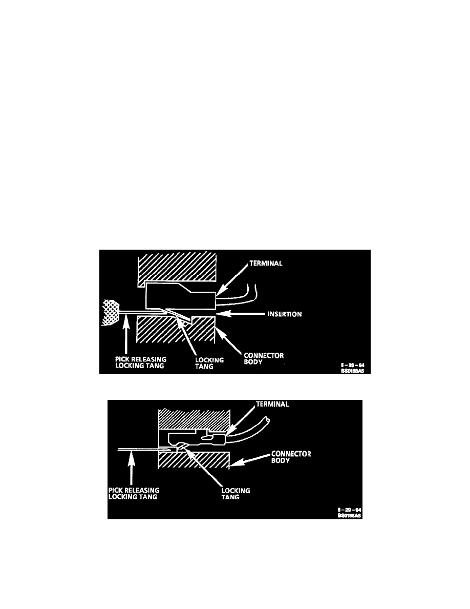
Push-to-Seat and Pull-to-Seat Connectors
Typical Push-to-seat Connector And Terminal
Typical Pull-to-seat Connector And Terminal
Follow the steps below to repair Push-to-Seat or Pull-to-Seat connectors. The steps are illustrated with typical connectors. Your connector may differ,
but the repair steps are similar. Some connectors do not require all the steps shown. Skip those that don't apply.
Step 1:
Remove any Connector Position Assurance (CPA) Locks . CPAs are designed to retain connectors when mated.