
Caprice V8-265 4.3L VIN W MFI (1995)
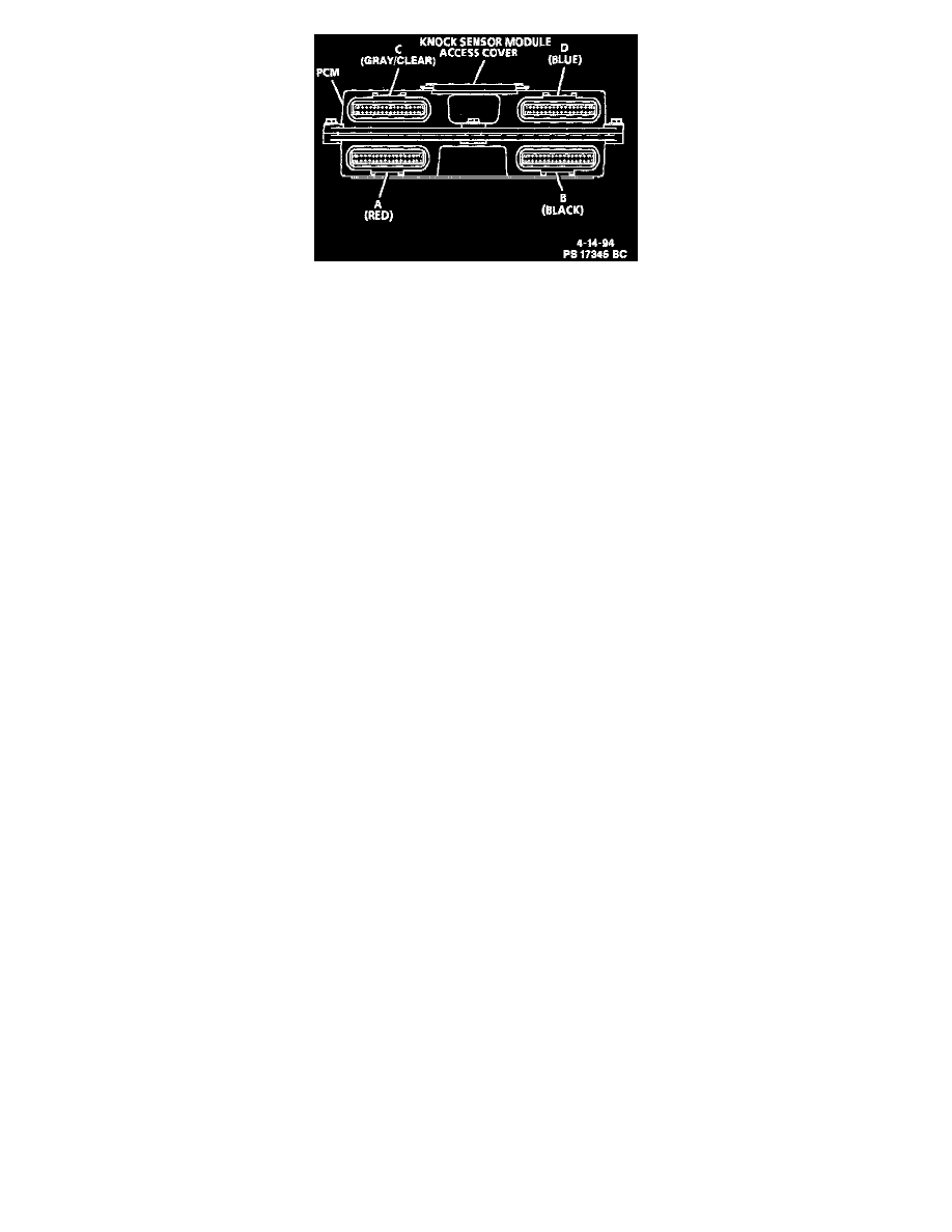
PCM Connectors
CAUTION: Do not backprobe Powertrain Control Module (PCM) connectors! The connectors are sealed for operation in an underhood environment.
Backprobing may damage the seal which could eventually cause the connector to fail due to corrosion.
This information applies to the PCM connector charts in the next four images. These charts may be used with the J 39700-A breakout box in conjunction
with J 39700-110 and J 39700-140 cables and high impedance digital multimeter J 39200 to obtain voltage present for each circuit listed. Install the
breakout box between the PCM connectors and the PCM. The breakout box PIN numbers correspond with the PCM connector PIN numbers. Voltage
may vary slightly, but should be very close. Certain exceptions are called out in the chart legend below.
The following conditions must be met before checking typical voltages:
Key "ON":
^
DVM negative (black) lead connected to a known good ground.
^
Scan tool "NOT" installed.
^
All accessories "OFF."
^
Battery fully charged.
Engine Running:
^
All conditions listed above.
^
Engine at normal operating temperature.
^
Engine at idle/closed throttle/operating in "Closed Loop."
^
In park or neutral.
CHART LEGEND
(1) Less than .5 volt when system enabled.
(2) Battery voltage for first two seconds with ignition "ON."
(3) Varies.
(4) Varies with temperature.
(5) Battery voltage when in gear.
(6) Less than .5 volt with brake pedal applied.
(7) Battery voltage with A/C "ON."
(8) Varies with altitude.
(9) Less than .5 volt with high power steering load.
(*) Less than .5 volt.