
Caprice RWD V8-305 5.0L (1992)
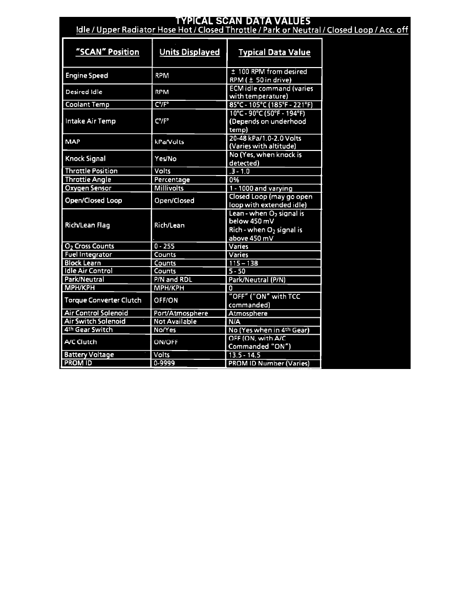
Typical Scan Data Values
Circuit Description:
The diagnostic circuit check is an organized approach to identifying a problem created by an electronic engine control system malfunction. It must be the
starting point for any driveability complaint diagnosis, because it directs the service technician to the next logical step in diagnosing the complaint.
Understanding the chart and using it correctly will reduce diagnostic time and prevent the unnecessary replacement of good parts
Test Description: Number(s) below refer to circled number(s) on the diagnostic chart.
1.
This step is a check for the proper operation of the "Service Engine Soon" light. The "SES" light should be "ON" steady.
2.
No "SES" light at this point indicates that there is a problem with the "SES" light circuit or the ECM control of that circuit.
3.
This test checks the ability of the ECM to control the "SES" light. With the diagnostic terminal grounded, the "SES" light should flash a Code 12
three times, followed by any trouble code stored in memory.
4.
Most of the procedures use a Scan Tool to aid diagnosis, therefore, serial data must be available. If a PROM error is present, the ECM may have
been able to flash Code 12/51, but not enable serial data.
5.
Although the ECM is powered up, a "Cranks But Will Not Run" symptom could exist because of an ECM or system problem.
6.
This step will isolate if the customer complaint is a "SES" light or a driveability problem with no "SES" light. An invalid code may be the result of
a faulty "Scan" tool, PROM or ECM.