
Caprice Wagon V8-350 5.7L (1994)
Knock Sensor Circuit
Functional Check:
The Tech 1 (or equivalent Scan tool) has several positions to check for diagnosing KS circuit. "Knock signal" is used to monitor the input signal
form the knock sensor. This position should display "YES" to indicate when a knock is being detected. "Knock retard" is the indication of how
much the PCM is retarding the spark.
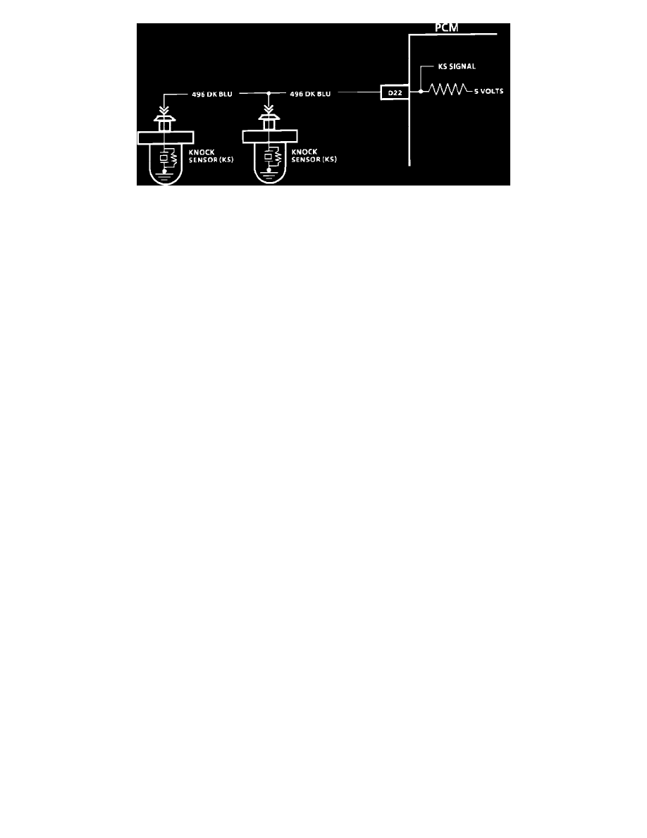
Circuit Description
The knock sensor system is used to detect engine detonation. The PCM will retard the spark timing based on signals form the knock sensor
module. The knock sensors produce an AC voltage which is sent to the KS module. The amount of AC voltage produced by the sensors is
determined by the amount of knock. The circuitry within each knock sensor causes the PCM's 5 volts to be pulled down so that under a no knock
condition, CKT 496 would measure about 1.5 volts.
Test Description
Numbers below refer to circled numbers on the diagnostic chart.
1. With engine idling, there should not be a knock signal present ant the PCM, because detonation is not likely under no load condition.
2. Tapping on the engines right or left exhaust manifold should simulate a knock signal to determine if the sensors are capable of detecting
detonation. If no knock is detected, try tapping on engine block closer to sensors before replacing a sensor.
3. If the engine has an internal problem which is creating a knock, the knock sensor may be responding to the internal failure.
4. This test determines if the knock sensor is faulty or if the problem is elsewhere in the circuit.
Diagnostic Aids
While observing knock signal on the Tech 1 (or equivalent Scan tool), there should be an indication that knock is present when detonation can be
heard. Detonation is most likely to occur under high engine load conditions.