
Caprice Wagon V8-350 5.7L (1994)
To find the correct wire size either find the wire on the schematic and convert the metric size to the equivalent AWG size or use an AWG wire
gage. If unsure about the wire size, begin with the largest opening in the wire stripper and work down until a clean strip of the insulation is
removed. Strip approximately 7.5 mm (5/16 in.) of insulation from each wire to be spliced. Be careful to avoid nicking or cutting any of the wires.
Check the stripped wire for nicks or cut strands. If the wire is damaged, repeat this procedure after removing the damaged section.
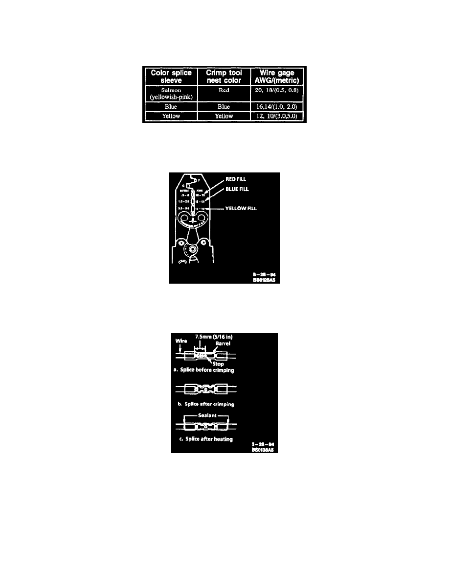
Crimp And Seal Splice Sleeve Chart
Step 4: Select and Position the Splice Sleeve
Select the proper splice sleeve according to wire size. The splice sleeves and tool tests are color coded (refer to Chart).
Hand Crimp Tool
Using the J 38125-8 splice crimp tool, position the splice sleeve in the proper color nest of the hand crimp tool. Place the splice sleeve in the nest
so that the crimp falls midway between the end of the barrel and the stop.
Seal Splice Sequence
The sleeve has a stop in the middle of the barrel to prevent the wire from going further. Close the hand crimper handles slightly to hold the splice
sleeve firmly in the proper nest.
Step 5: Insert Wires into Splice Sleeve and Crimp
Insert the wire into the splice sleeve until it hits the barrel stop and close the handles of the J 38125-8 crimper tightly until the crimper handles
open when released. The crimper handles will not open until the proper amount of pressure is applied to the splice sleeve. Repeat steps 4 and 5 for
opposite end of the splice.
Step 6: Shrink the Insulation Around the Splice
Using the Ultratorch J 38125-5 (follow instructions that accompany Ultratorch), apply heat where the barrel is crimped. Gradually move the heat