
Caprice Wagon V8-350 5.7L (1994)
Important:
Holes to be elongated in a forward direction are those on the rear axle lower control arm bracket, on the side of the vehicle that had the smaller
dimension measured in Step 2.
4.
Disconnect and remove rear stabilizer shaft, if equipped.
5.
Remove lower control arm to axle assembly attaching bolt and swing control arm downward on side of axle determined in Step 3 to require hole
elongation.
6.
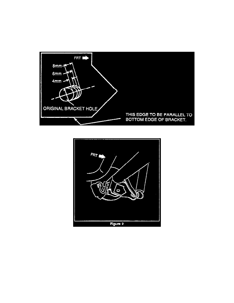
Cut out template along outer outline. Cut out hole in template indicated as original bracket hole. (Reference Figure 5).
7.
Position template on inboard surface of axle control arm bracket as shown in Figure 2. Align hole in template with hole in bracket and insure
bottom edge of template is parallel to bottom edge of bracket.
8.
Transfer from the template to the bracket the amount hole is to be elongated along axis indicated on template.