
Cavalier L4-2.2L VIN 4 (1998)
Idle Air Control (IAC) Valve: Description and Operation
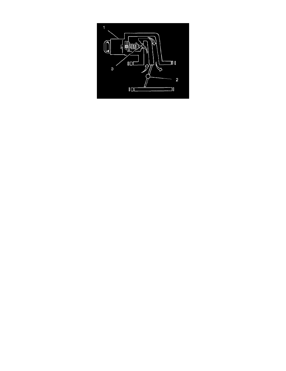
Engine idle speed is controlled by the PCM through the IAC valve (1) mounted on the throttle body. The PCM sends voltage pulses to the IAC valve
motor windings causing the IAC valve pintle (3) to move IN (toward the seat) or OUT (away from the seat) a given distance (a step or count) for each
pulse. The commanded location (steps away from the seated position) can be observed as a number of counts displayed on a scan tool. The pintle
movement controls the airflow around the throttle valve (2), which in turn, controls engine idle speed: Pintle Extended=Decrease RPM=Lower Counts.
Pintle Retracted=Increase RPM=Higher Counts.
The controlled or desired idle speed for all engine operating conditions is programmed into the EEPROM of the PCM. The programmed engine speeds
are based on coolant temperature, park/neutral switch status, vehicle speed, battery voltage, and A/C refrigerant pressure (if equipped).
The PCM learns the proper IAC valve positions to achieve warm, stabilized idle speeds (RPM), desired for the various conditions (PIN or Drive, A/C
ON or OFF, if equipped). This information is stored in PCM Keep Alive memories (information is retained after ignition is OFF). All other IAC valve
positioning is calculated based on these memory values. As a result, engine variations due to wear, and variations in minimum throttle valve position
(within limits) do not affect engine idle speeds. This system provides correct idle control under all conditions. This also means that disconnecting power
to the PCM can result in incorrect idle control or the necessity to partially depress the accelerator when starting, until the PCM relearns idle control.
^
Engine idle speed is a function of total airflow into the engine based on IAC valve pintle position plus throttle valve opening plus calibrated
vacuum loss through accessories.
^
The minimum throttle valve position is set at the factory with a stop screw. This setting allows enough air flow by the closed throttle valve to
cause the IAC valve pintle to be positioned a calibrated number of steps (counts) from the seat during controlled idle operation. The minimum
throttle valve position for this engine is not the same as the minimum idle speed associated with other fuel injected engines. The throttle stop
screw is tilled at the factory following an adjustment.
IMPORTANT: Do Not try to remove the filler and readjust the stop screw. Misadjustment may set a DTC P0506 or a DTC P0507.
^
The PCM normally resets the IAC valve pintle position once during each ignition cycle when vehicle speed increases above 20 mph on
moderate acceleration. During the reset, the PCM commands the IAC valve pintle to retract completely, then move IN to the seated position
(to establish the zero count position), and then back out to the desired position. The IAC is relearned only once per ignition cycle.
^
The IAC valve also can be reset without driving the vehicle by using this service procedure:
1. Turn ignition switch to the ON position (engine OFF).
2. Turn ignition OFF for ten seconds.
3. Start engine and check for proper idle operation.
^
Whenever the IAC valve is disconnected and reconnected while the engine is running, the resulting IAC valve counts may not correspond with
the actual IAC valve pintle position. When servicing the IAC valve, it should only be disconnected or connected after the ignition has been
OFF for at least 10 seconds. This allows time for the PCM to move the IAC valve to the 150 count position where it is parked while the
ignition is OFF. Whenever this procedure is not followed, the PCM will lose track of IAC valve position resulting in starting or idle control
problems until the IAC valve is reset and pintle position is relearned.
^
IAC system problems may cause improper idle speeds, resulting in a DTC P0506 or a DTC P0507. The DTC P0506 or the DTC P0507 tables
should be used to diagnose these problems.