
Cavalier L4-2.2L VIN 4 (1998)
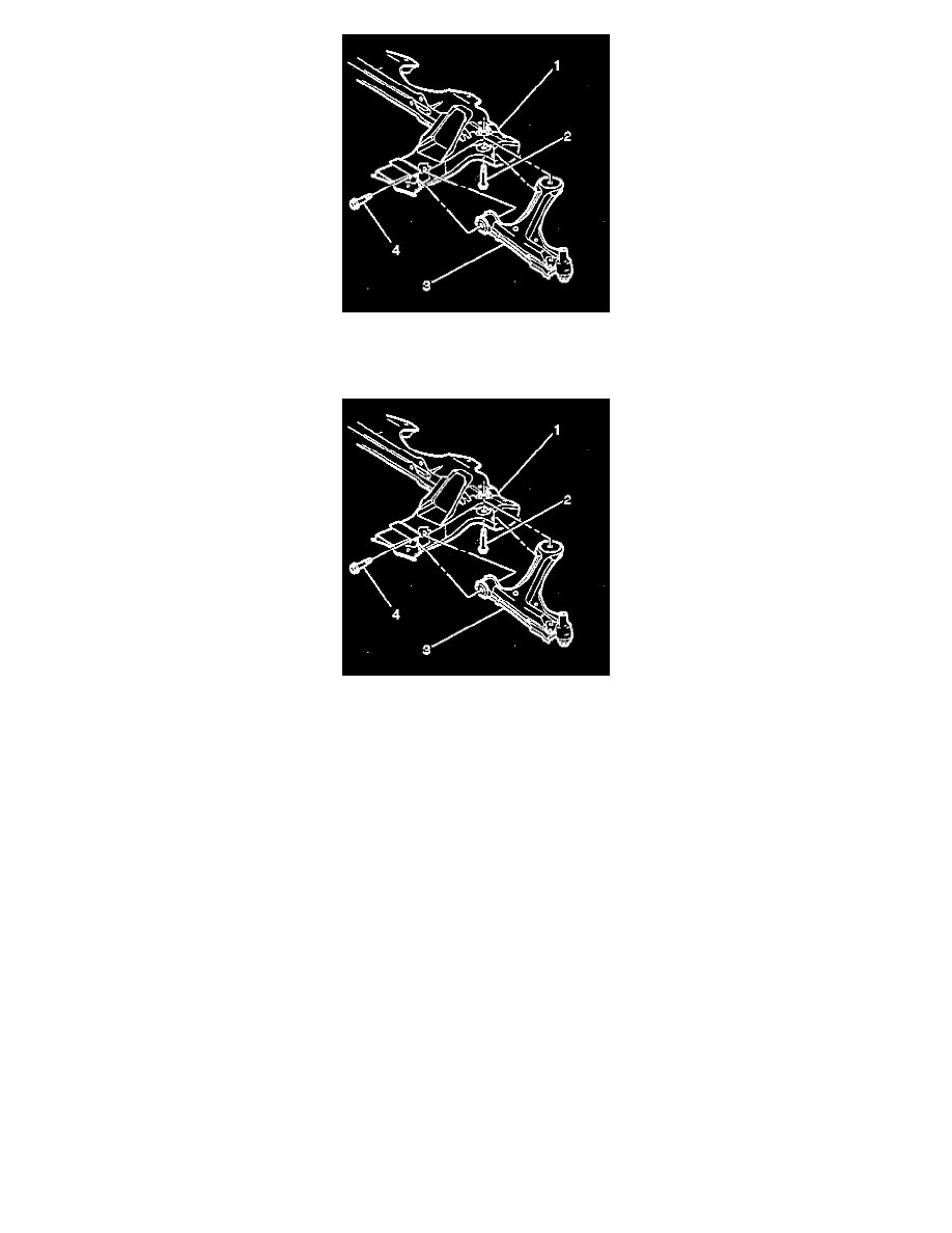
14. Remove the control arms (3) from the crossmember (1).
INSTALLATION PROCEDURE
1. Install the control arms (3) to the crossmember (1). Snug the bolts.
2. Install the crossmember. Finger tighten all of the bolts.
NOTICE: Always use the correct fastener in the proper location. When you replace a fastener, use ONLY the exact part number for that
application. The manufacturer will call out those fasteners that require a replacement after removal. The manufacturer will also call out the
fasteners that require thread lockers or thread sealant. UNLESS OTHERWISE SPECIFIED, do not use supplemental coatings (paints, greases, or
other corrosion inhibitors) on threaded fasteners or fastener joint interfaces. Generally, such coatings adversely affect the fastener torque and joint
clamping force, and may damage the fastener. When you install fasteners, use the correct tightening sequence and specifications. Following these
instructions can help you avoid damage to parts and systems.
3. Tighten the bolts in the sequence shown below:
Tighten
^
Tighten the crossmember support left rear outboard bolt to 110 Nm (71 ft. lbs.) plus a 90° rotation.
^
Tighten the crossmember support right rear outboard bolt to 110 Nm (71 ft. lbs.) plus a 90° rotation.
^
Tighten the crossmember support upper front bolts to 90 Nm (66 ft. lbs.) plus a 90° rotation.
^
Tighten the crossmember support rear inboard bolts to 110 Nm (71 ft. lbs.) plus a 90 rotation.
Important: Do not loosen the nut any time during the installation.