
Cavalier L4-2.2L VIN F (2004)
11. Snap the tumblers into place with light hand pressure.
12. Inspect for the correct loading of the tumblers (6) by inserting the key into the cylinder (5). All of the tumblers should be flush with the lock
cylinder.
13. Lightly lubricate the tumbler (6) surfaces using the provided lubrication.
14. Install the lock cylinder (5) into lock cylinder housing (12).
IMPORTANT: The key must be in the lock cylinder (5) when performing this step.
15. Rotate the lock cylinder (5) counterclockwise until it stops.
16. Remove the key from the lock cylinder (5).
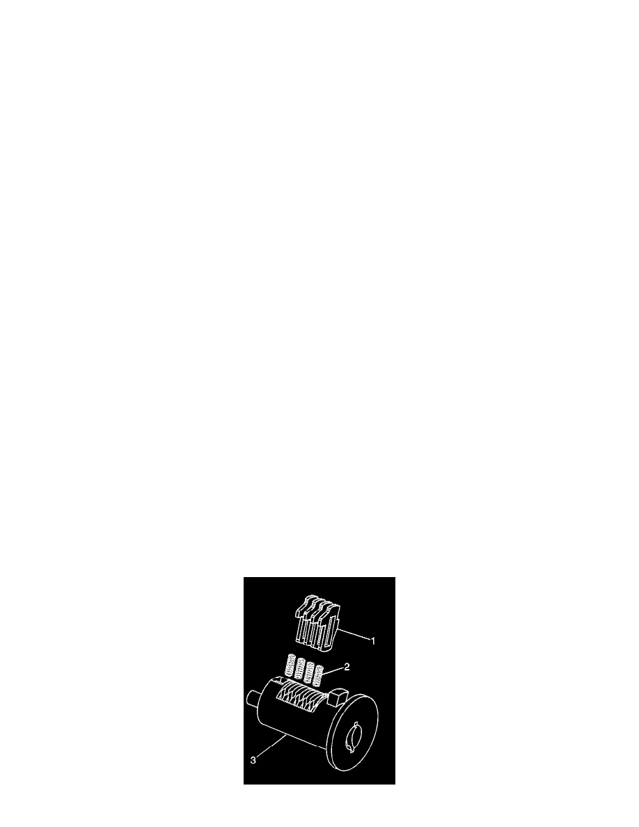
17. Insert two plate springs (3) into the spring wells in the head of the lock cylinder (5).
18. Line up the shutter pins with the pin pockets and snap shutter (2) onto the lock cylinder (5), by pressing on the face of the shutter with light hand
pressure.
19. Note the position of the two dimples on the side of the lock cylinder housing.
20. Align the cut-out on dust cover (1) with widest lug on the lock cylinder housing (12).
21. Install the dust cover (1) over head of the lock cylinder housing (12).
22. Using a small punch or drift, stake the dust cover (1) onto the lock cylinder housing (12) at the 2 dimples on the side of the lock cylinder.
23. Align the widest slot on the lock cylinder housing (12) with the widest rib in the inside diameter of the base (7).
24. Install the cylinder and housing (12) into the back of the base assembly (7).
Use thumb pressure, as necessary.
25. Install the compression spring (13) into the back of the base assembly (7)
26. Assemble the torsion spring (11) onto the lock cylinder shaft (9).
27. Slide the torsion spring (11) toward the large end of the shaft (9) with the interior leg of the spring facing the larger end of the shaft.
28. Align the ribs on the inner surface of the switch (10) bore with the grooves on the shaft (9).
29. Install the shaft (9) through the switch (10) to the following position:
-
The wires on the switch (10) face the large end of the shaft (9).
-
The large groove on the shaft (9) is 180 degrees from the switch wires (10).
30. Install switch and shaft (1 and 3) into the rear of the retainer (14).
31. Looking at the large end of shaft (9), rotate shaft counterclockwise until it stops.
32. Align the retainer (14) to the base (7).
Align the wide slot on the retainer to the widest rib on the inner surface of the base.
33. Push the retainer (14) inward, while turning the key in order to align the shaft (9).
34. Push in the retainer (14) to compress spring (13).
Turn the retainer (14) approximately 1/8 turn counterclockwise.
35. Engage the torsion spring (11) onto the lug on the retainer (14).
36. Install the retainer clip (8) onto the base (7).
37. Install the gasket onto the base (7).
38. Inspect the operation of the lock assembly. The torsion spring (11) should provide a counterclockwise snap back.
ASSEMBLING AND CODING IP STORAGE COMPARTMENT LOCK CYLINDER
The IP storage compartment lock only uses 4 of the 10 cut positions 7-10. A retainer tumbler is used in the IP storage compartment lock to retain the
lock cylinder in the latch assembly. This retainer tumbler is not moved by the key. The retainer tumbler occupies the slot closest to the head of the IP
storage compartment lock cylinder and should come already installed in the cylinder.