
Cavalier L4-2.2L VIN F (2004)
Ignition Control Module: Description and Operation
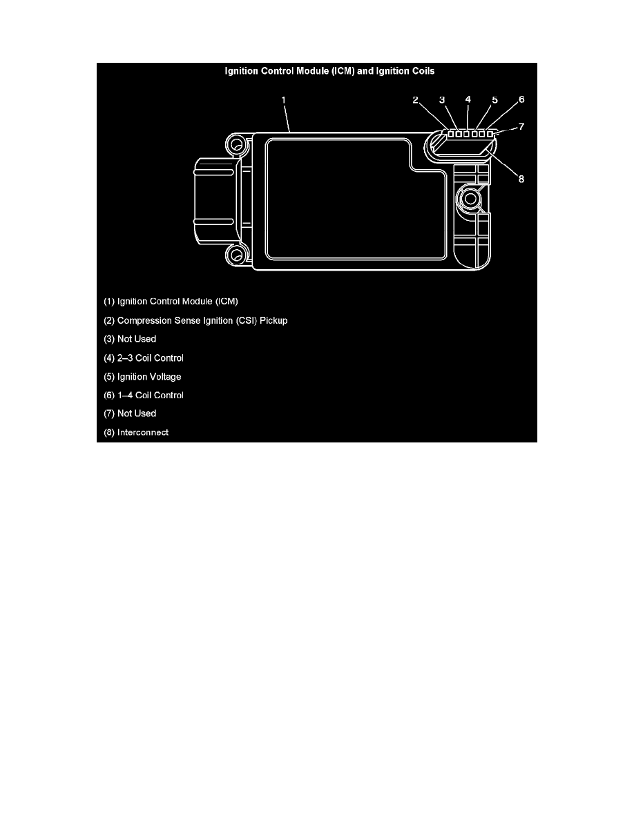
IGNITION CONTROL MODULE (ICM) AND IGNITION COILS
1. Ignition Control Module (ICM)
2. Compression Sense Ignition (CSI) Pickup
3. Not Used
4. 2-3 Coil Control
5. Ignition Voltage
6. 1-4 Coil Control
7. Not Used
8. Interconnect
Each ignition coil is responsible for supplying secondary energy to a pair of spark plugs. The ignition control signals output by the PCM are amplified
by the ICM in order to fire each coil. The spark events are triggered by the ICM, but the module has no influence on spark timing. The ICM is also
responsible for detecting and supplying a camshaft position (CMP) signal pulse to the PCM to be used for sequential fuel injection. This ignition
system does not use a conventional CMP sensor that detects valve train position. The ICM detects when either cylinder 1 or cylinder 3 has fired on the
cylinders compression stroke using sensing circuitry integrated within each coil. The sensing circuit detects the polarity and the strength of the
secondary voltage output, the higher output is always at the event cylinder. The ICM sends a CMP signal to the PCM based on the voltage difference
between the event and waste cylinder firing energy.
This system is called compression sense ignition. By monitoring the camshaft position and crankshaft position (CKP) signals the PCM can accurately
time the operation of the fuel injectors.