
Cavalier/Z24 L4-138 2.3L DOHC VIN D MFI (1995)
Engine Control Module: Description and Operation
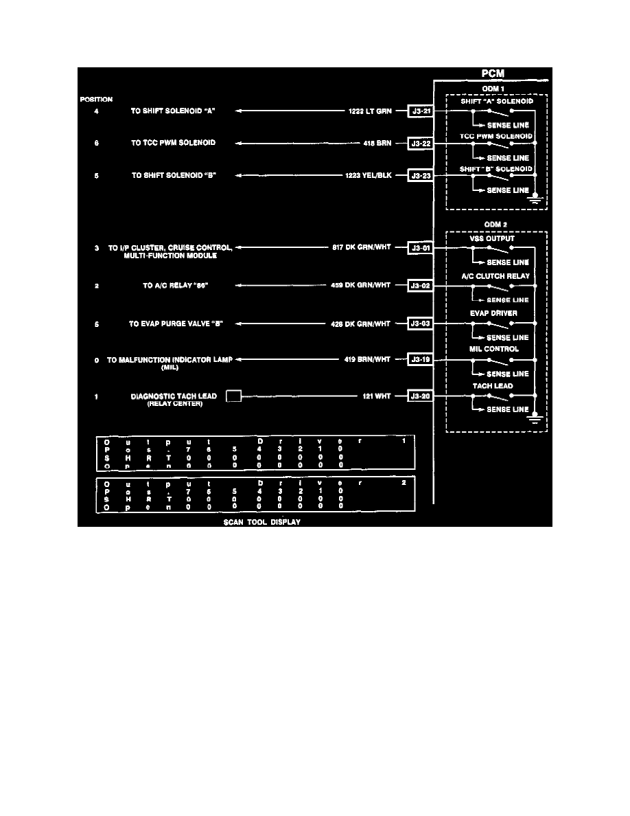
PCM Outputs (Qdsm & Odm)
PCM Outputs
DESCRIPTION
The Powertrain Control Module (PCM) controls most components with electronic switches which complete a ground circuit when turned "ON."
These switches are arranged in groups of 4 and 7, called either a surface mounted Quad Driver Module (QDSM), which can independently control
up to 4 outputs (PCM) terminals or Output driver Modules (ODMs) which can independently control up to 7 outputs. Not all outputs are always
used.
OPERATION
When and output is "ON," the terminal is grounded and its voltage will normally be low. When an output is "OFF," its terminal voltage normally
will be high.
QDSMs and ODMs are fault protected. If a relay or solenoid is shorted, having very low or zero resistance, or if the control side of the circuit is
shorted to voltage, it would allow too much current flow into the QDSM/ODM. The QDSM/ODM senses this and the output is turns "OFF" or
internal resistance increases to limit current flow and protect the ODSM/ODM. The result is high output terminal voltage when it should be low. If
the circuit for B+ or the component is open, or the control side of the circuit is shorted to ground, terminal voltage will be low, even when the
output is commanded "OFF." Either of these conditions is considered to be a QDSM/ODM fault.
QDSMs and ODMs also have a fault line to indicate the presence of a current fault to the PCM's central processor. A scan tool displays the status
of the ODM fault lines as "0" = OK, "1" = Fault.