
Cobalt L4-2.0L SC VIN P (2005)
Correction
Important
Prior to any work being performed, contact your District Service Manager/Warranty Manager for repair approval.
For 2005-2007 Chevrolet Cobalt SS and 2004-2007 Saturn ION Redline
If this repair is approved by the District Service Manager/Warranty Manager, replace the transmission assembly. During removal of the transmission,
replace the front (GM P/N 20814994) and rear (GM P/N 20814995) powertrain mounts. Refer to SI for the procedures on replacing the transmission
front and rear mounts.
For 2008-2009 Chevrolet Cobalt SS and 2008-2009 Chevrolet HHR SS
If this repair is approved by the District Service Manager/Warranty Manager, replace the transmission assembly. During removal of the transmission,
inspect the following parts and replace if necessary (excluding tires):
-
Tire wear (excessive or uneven) front vs. rear or rubber debris in the front wheel house liner area.
-
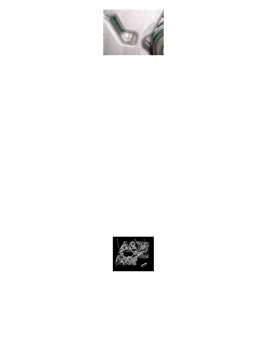
Inspect the upper right side mount for fluid leaks or (rubber) structural failure.
-
Front and rear powertrain mounts, if necessary (refer to SI for the procedure on replacing the transmission front and rear mounts).
Important
Verify that the 12-volt battery has a battery charge of 12 to 16 volts. The battery must be able to maintain a charge during programming. Only
use approved Midtronics 165-PCS charger or equivalent to maintain proper battery voltage during programming. The J 2534 MDI will
reprogram the modules in less time than the Tech 2(R) scan tool.
Reprogram the ABS with a updated service calibration using the TIS2WEB Service Programming System (SPS) application. Make sure your Tech 2(R)
is updated with the latest software version. The ABS calibration is available to dealerships in TIS2WEB (website version of TIS). Refer to Electronic
Brake and/or Traction Control Module Reprogramming with SPS procedure in SI.
Install Clutch Actuator Pipe Elbow Assembly (P/N 24252286)
1. Disconnect the negative battery cable. Refer to Battery Negative Cable Disconnection and Connection.
2. Remove the cover from the underhood electrical center.
3. Remove the underhood electrical center bracket from the vehicle and reposition the electrical center (1) to access the bracket. Refer to Underhood
Electrical Center or Junction Block Bracket Replacement.
Note
Rotate the hose to stop brake fluid from running out of it.
4. Disconnect the hydraulic clutch hose (3) from the clutch actuator cylinder (2) and the clutch master cylinder (1).
5. Install the clutch actuator pipe elbow assembly, GM P/N 24252286.
6. Connect the hydraulic clutch hose (3) to the clutch actuator cylinder (2).
7. Bleed the clutch hydraulic system. Refer to Hydraulic Clutch Bleeding.
8. Install the underhood electrical center bracket to the vehicle and install the electrical center into position on the bracket. Refer to Underhood
Electrical Center or Junction Block Bracket Replacement.
9. Connect the negative battery cable. Refer to Battery Negative Cable Disconnection and Connection.