Cobalt L4-2.0L SC VIN P (2005)

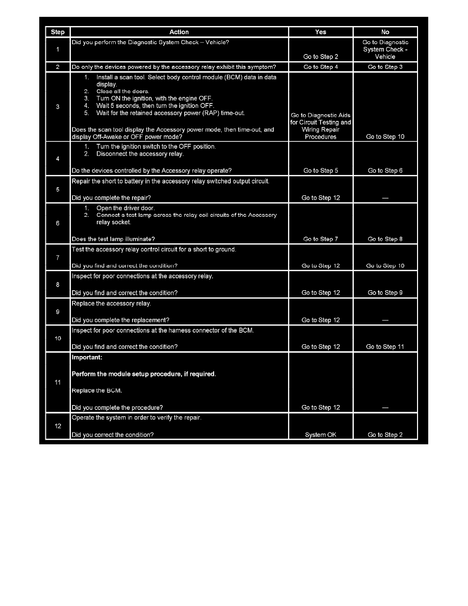
Steps 1-12
Power Mode Mismatch
POWER MODE MISMATCH
CIRCUIT DESCRIPTION
Normal vehicle serial data communications and the control modules operations will not begin until the system power mode has been identified.
Discrete wires from the ignition switch contacts are monitored by a module which acts as the power mode master (PMM) in order to determine the
correct power mode. The module which is the PMM communicates the system power mode to all modules on the serial data lines. Refer to Body
Control System Description and Operation to identify which module is the PMM and the applicable power mode look up table.
TEST DESCRIPTION
