
Cobalt L4-2.2L (2008)
27. Rotate the body of the J 45405 until it bottoms against the die cage.
28. While guiding the finishing cone into the exposed end of pipe to be flared, operate the lever of the J 45405 until the finishing cone bottoms
against the dies.
29. Rotate the hydraulic fluid control valve counterclockwise to the open position to allow the hydraulic forming ram to retract.
30. Loosen the die clamping screw and remove the dies and pipe.
31. If necessary, lightly tap the dies until the die halves separate.
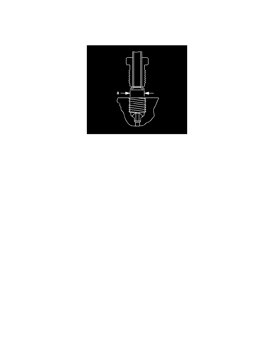
32. Inspect the brake pipe flare for correct shape and diameter (a).
*
6.92 mm (0.272 in) within 0.18 mm (0.007 in) flare diameter for 4.76 mm (3/16 in) diameter pipe
*
8.92 mm (0.351 in) within 0.18 mm (0.007 in) flare diameter for 6.35 mm (1/4 in) diameter pipe
Important: When installing the pipe, maintain a clearance of 19 mm (3/4 in) from all moving or vibrating components.
33. If necessary, using the removed section of brake pipe as a template, shape the new pipe with a suitable brake pipe bending tool.
34. Install the pipe to the vehicle with the appropriate brake pipe unions, as required.
35. If previously released, secure the brake pipe to the retainers.
36. Bleed the hydraulic brake system. Refer to Hydraulic Brake System Bleeding (Pressure) (See: Brake Bleeding/Service and Repair)Hydraulic
Brake System Bleeding (Manual) (See: Brake Bleeding/Service and Repair) .
37. With the aid of an assistant, inspect the brake pipe flares for leaks by starting the engine and applying the brakes.