
Cobalt L4-2.2L (2008)
Important: Ensure that the set gage ring EN 45680-862 surfaces are clean.
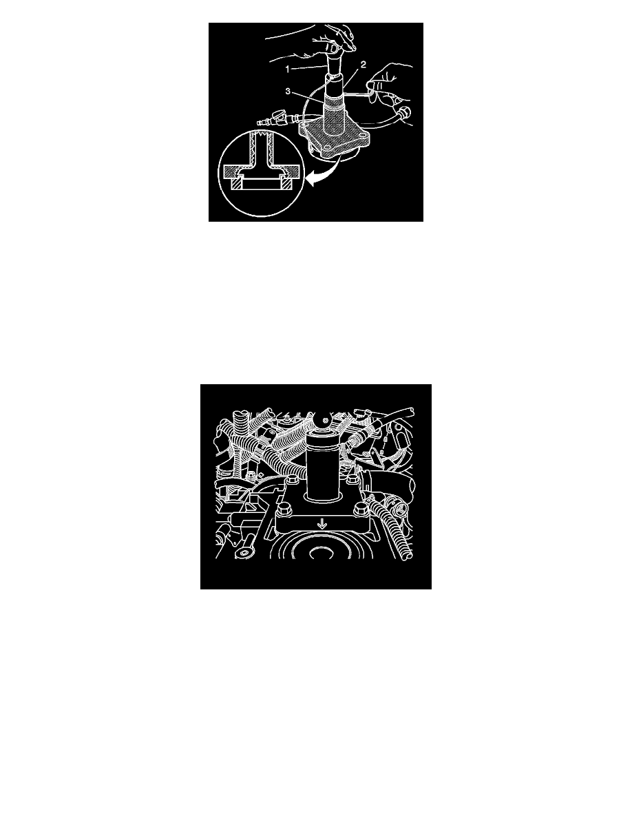
6. Carefully position trim tool assembly EN 45680-861 onto the set gage ring EN 45680-862.
7. Loosen the shaft collar screw (2).
8. Push the shaft collar (2) downward using the trim tool preloader (1) until the shaft collar is positioned against the top of the flange bearing (3).
Important: Once this procedure is done, it is not necessary to reset the trim tool assembly EN 45680-861 height until the blades are worn
or damaged.
9. Apply downward pressure on the collar and inner drive shaft using the trim tool preloader (1), then tighten the shaft collar screw.
Tighten the shaft collar screw to 19 N.m (14 lb ft).
10. Place trim tool assembly EN 45680-861 onto the cylinder to be trimmed with the directional arrow pointing in line with the crankshaft centerline
and the front of the block.
11. Install the 4 bolts EN 45680-864 into the cylinder head bolt holes in the block.
Tighten the bolts to 20 N.m (15 lb ft).