
Cobalt L4-2.2L (2008)
Ignition Switch Lock Cylinder: Service and Repair
Key and Lock Cylinder Coding
Tools Required
*
BO-47869 Ignition Lock Cylinder Replacement Tool
*
BO-48370 Lock Cylinder Cap Installer
Important: BO-47869 is used for the ignition lock cylinder. BO-48370 is used for the rear compartment lock cylinder.
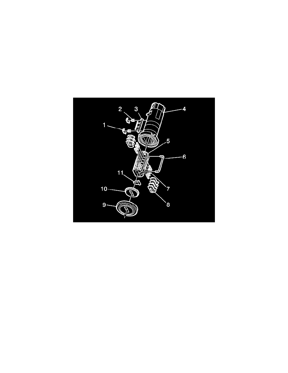
Ignition Lock Cylinder
The ignition lock cylinder used 7 of the 10 key cut positions, 4-10 when counting from the key head. The tumbler (3) orientations alternate in adjacent
locations from side to side with 3 on one side and 4 on the other.
Caution: Wear safety glasses in order to avoid eye damage.
Important: The ignition lock cylinder tumblers (3) are not self-retaining and must be held in place if the key is not fully inserted into the
lock cylinder.
1. Hold the uncoded cylinder plug (5) positioned so the side with the sidebar slot is facing to the left and the 3 spring holes are on top.
2. Insert one tumbler spring (7) each into the 3 tumbler spring holes.
3. The first tumbler to be loaded will be key cut position number 5, the fifth number in the key code. Determine the cut depth at this position and
install the corresponding tumbler (8) into the tumbler slot second from the front of the cylinder plug (5) (the end where the key is inserted).
4. In the same manner, determine the cut depth and corresponding tumbler and install the 2 remaining tumblers (8) into the tumbler slots located at
key cut positions 7 and 9.
5. Check for correct loading by holding the tumblers (8) in position and fully inserting the matching key into the cylinder plug (5). All tumblers
should be flush with the outside diameter of the cylinder plug.
6. Rotate the cylinder plug (5) so that the side with the sidebar slot is facing to the right and then remove the matching key. Remember the tumblers
(8) are not self-retaining and must be held in place.
7. Insert one tumbler spring (7) each into the 4 tumbler spring holes.
8. The first tumbler to be loaded will be key cut position number 4. Determine the cut depth at this position and install the corresponding tumbler (8)
into the tumbler slot nearest the front of the cylinder plug (5).
9. In the same manner, determine the cut depth and corresponding tumbler and install the 3 remaining tumblers (8) into the slots located at key cut
positions 6, 8, and 10.
10. Check for correct loading by holding the tumblers (8) in position and fully inserting the matching key into the cylinder plug assembly (5). All
tumblers should be flush with the outside diameter of the cylinder plug.
11. Lightly lubricate tumbler (8) surfaces using the lubrication provided.
12. Hold the cylinder plug (5) positioned so the side with the sidebar slot is facing to the left. Insert the U-shaped plunger shaft (6) into the grooves on
the right side of the cylinder plug.