
Cobalt L4-2.4L VIN B (2006)
putting a strain on the wire. If the wire is not long enough, splice a small length of the same gage wire to the existing wire, then crimp the new terminal
on the added wire.
1. Cut the wire as close to the damaged terminal as possible.
2. Strip 5 mm (3/16 in) of insulation from the wire.
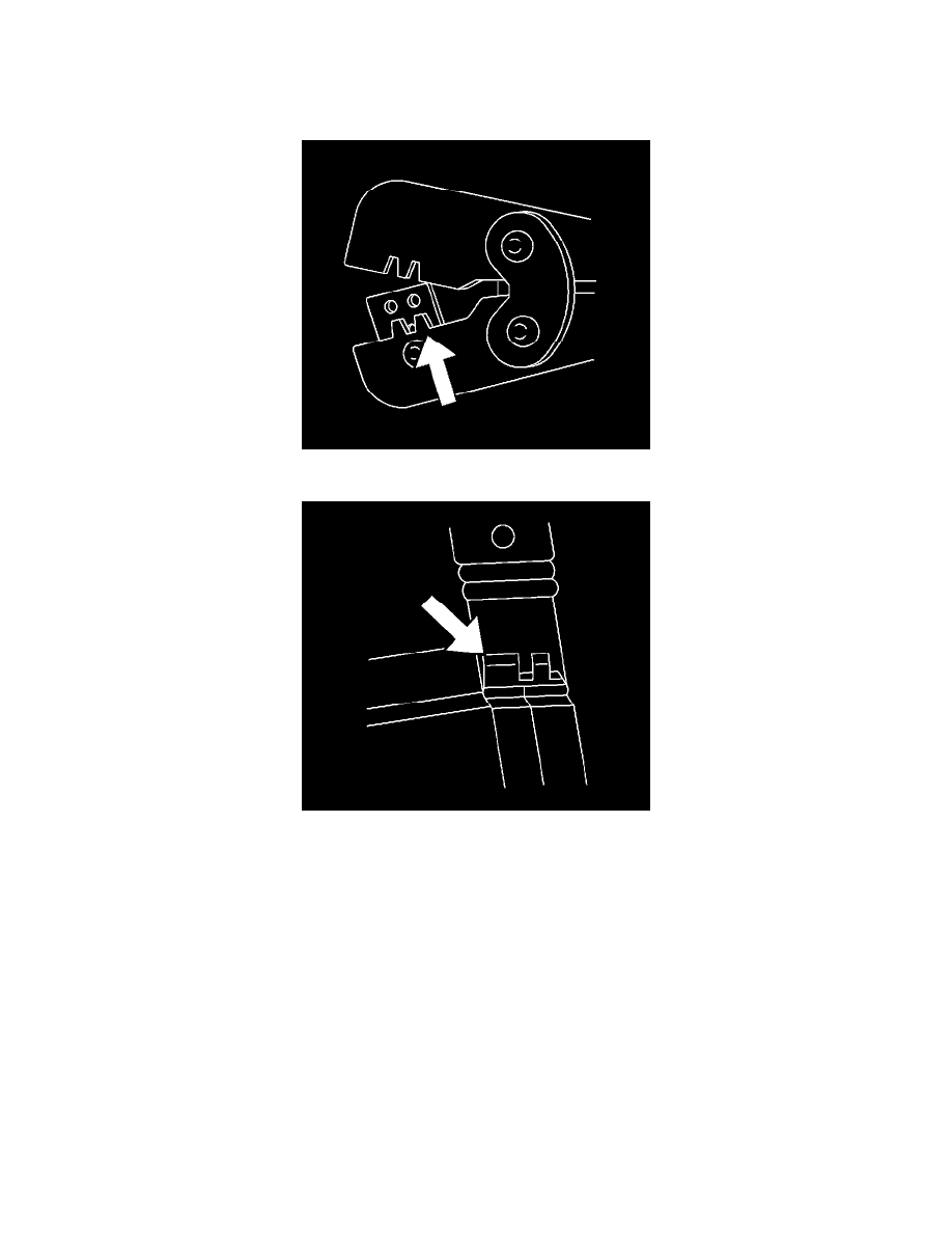
3. Depress the spring loaded locator of the crimping tool until the terminal holder is completely visible.
4. Insert terminal into the appropriate terminal holder until it hits bottom and stops. The correct terminal holder is determined by the wire size. Also
ensure that the terminals wings are pointing towards the former on the tool and the release locator.
5. Insert the stripped cable into the terminal. Insulation should be visible on both sides of the terminal insulation wings.
6. Compress the handles until the ratchet automatically releases.
7. Place the terminal into the appropriate cavity and assemble the connector.
Micro-Pack 100W Connectors
MICRO-PACK 100W CONNECTORS
TERMINAL REMOVAL PROCEDURE
1. Disconnect the connector from the component or separate the connector halves for in-line connectors.