
Colorado 2WD L5-3.5L VIN 6 (2005)
35. Rotate the hydraulic fluid control valve counterclockwise to the open position to allow the hydraulic forming ram to retract.
36. Loosen the die clamping screw and remove the dies and pipe.
37. If necessary, lightly tap the dies until the die halves separate.
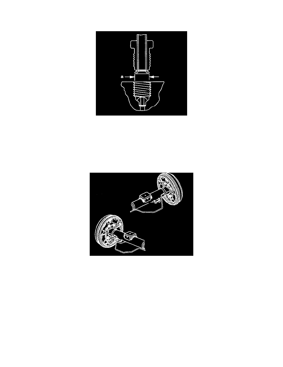
38. Inspect the brake pipe flare for correct shape and diameter (a).
Specification
^
6.92 mm (0.272 inch) ± 0.18 mm (0.007 inch) flare diameter for 4.76 mm (3/16 inch) diameter pipe
^
8.92 mm (0.351 inch) ± 0.18 mm (0.007 inch) flare diameter for 6.35 mm (1/4 inch) diameter pipe
39. If necessary, using the removed section of brake pipe as a template, shape the new pipe with a suitable brake pipe bending tool.
Important When installing the pipe, maintain a clearance of 19 mm (3/4 inch) from all moving or vibrating components.
Installation Procedure
1. Using your fingers, tighten the brake pipe to the wheel cylinder by hand.
Notice: Refer to Fastener Notice in Service Precautions.
2. Using a backup wrench, tighten the brake pipe fitting.
^
Tighten the brake pipe fitting to 19 Nm (14 ft. lbs.).
3. Using your fingers, tighten the brake pipe to the wheel cylinder by hand.
Notice: Refer to Fastener Notice in Service Precautions.
4. Tighten the brake pipe fitting.
^
Tighten the brake pipe fitting to 19 Nm (14 inch lbs.).