
Colorado 2WD L5-3.5L VIN 6 (2005)
Important: Before using trim tool assembly EN 45680-411 the height of the cutting blades must be set to the proper specification. The proper
specification is that the cylinder bore sleeve flange must be flush to +0.02 mm (0.0008 in) above the block deck surface.
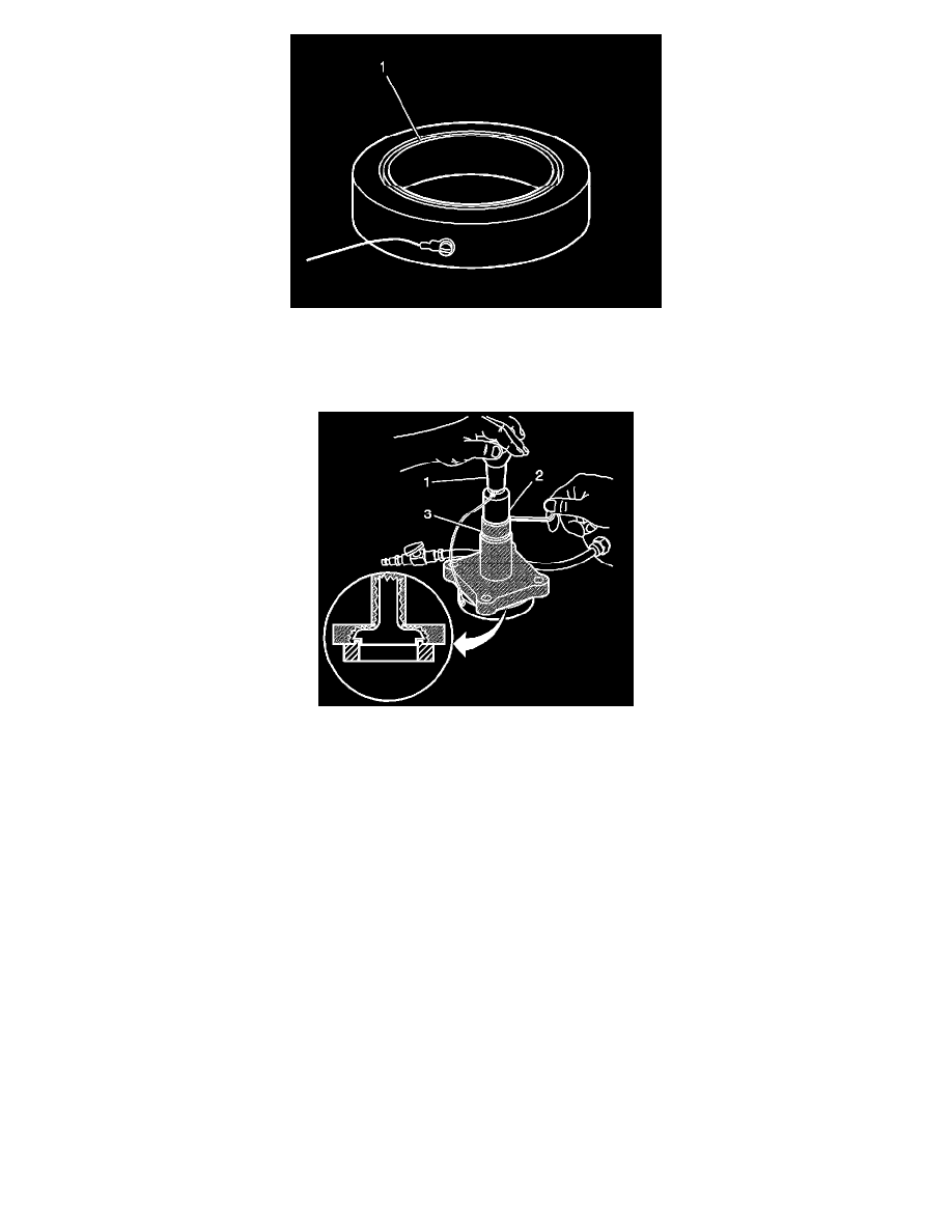
5. The groove side of the set gage ring EN 45680-412 (1) should be positioned upward on a flat surface.
Important: Ensure that the set gage ring EN 45680-412 surfaces are clean.
6. Carefully position trim tool assembly EN 45680-411 onto the set gage ring EN 45680-412.
7. Loosen the shaft collar screw (2).
8. Push the shaft collar (2) downward using the trim tool preloader (1) until the shaft collar is positioned against the top of the flange bearing (3).
Important: Once this procedure is done, it is not necessary to reset the trim tool assembly EN 45680-411 height until the blades are worn or
damaged.
9. Apply downward pressure on the collar and inner drive shaft using the trim tool preloader (1), then tighten the shaft collar screw.
Tighten
Tighten the shaft collar screw to 19 Nm (14 lb ft).