
Colorado 4WD L4-2.9L (2008)
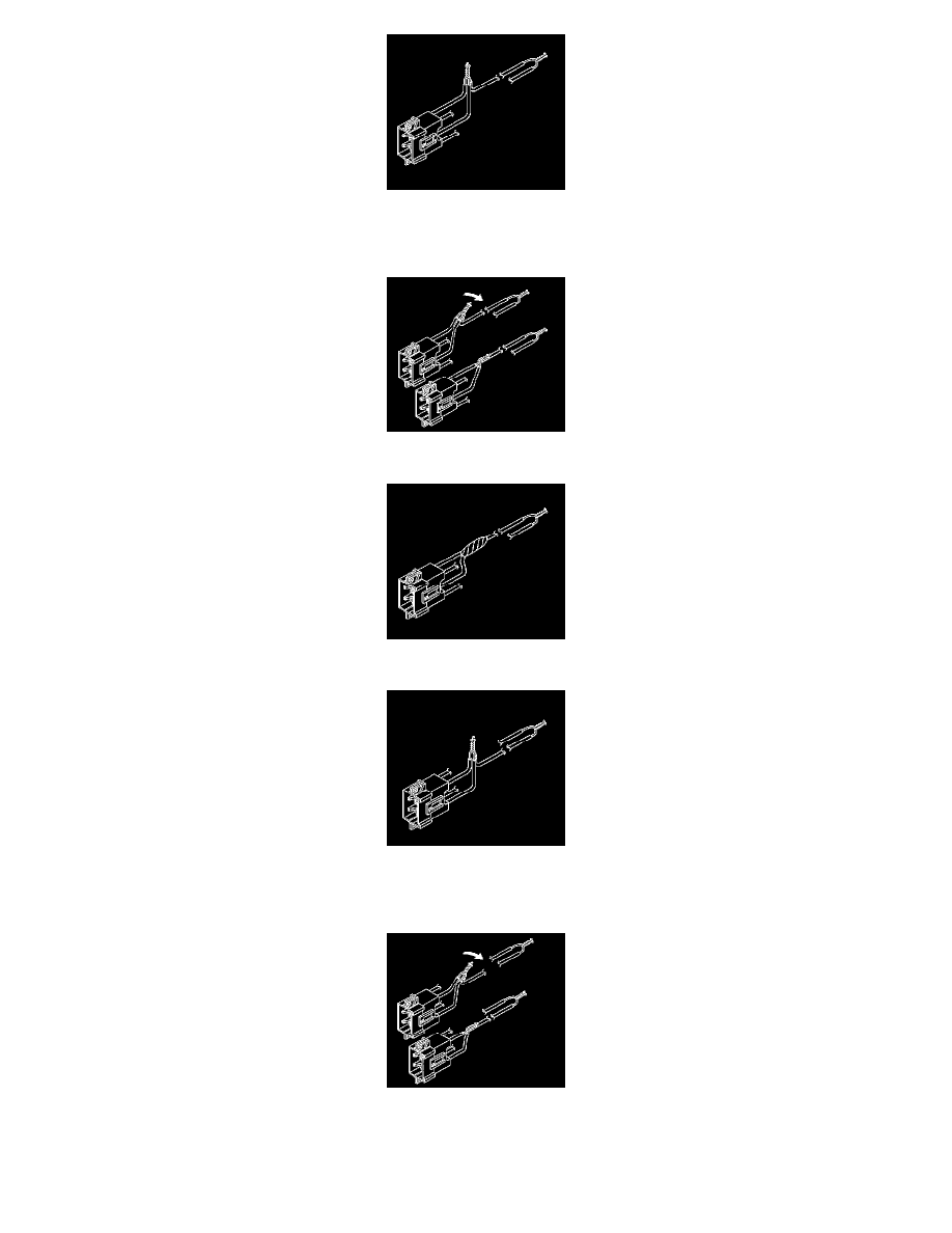
40. Twist together the 2 connector wire leads from the high circuits from both stages of the I/P module to one set of deployment wires. Refer to
Component Connector End Views (See: Diagrams/Connector Views) in order to determine the correct circuits.
41. Inspect that the 3-wire connection is secure.
42. Bend flat the twisted connection.
43. Secure and insulate the 3-wire connection to the deployment harness using electrical tape.
44. Twist together the 2 connector wire leads from the low circuits from both stages of the I/P module to one set of deployment wires. Refer to
Component Connector End Views (See: Diagrams/Connector Views) in order to determine the correct circuits.
45. Inspect that the 3-wire connection is secure.
46. Bend flat the twisted connection.