Colorado 4WD L5-3.5L VIN 6 (2005)

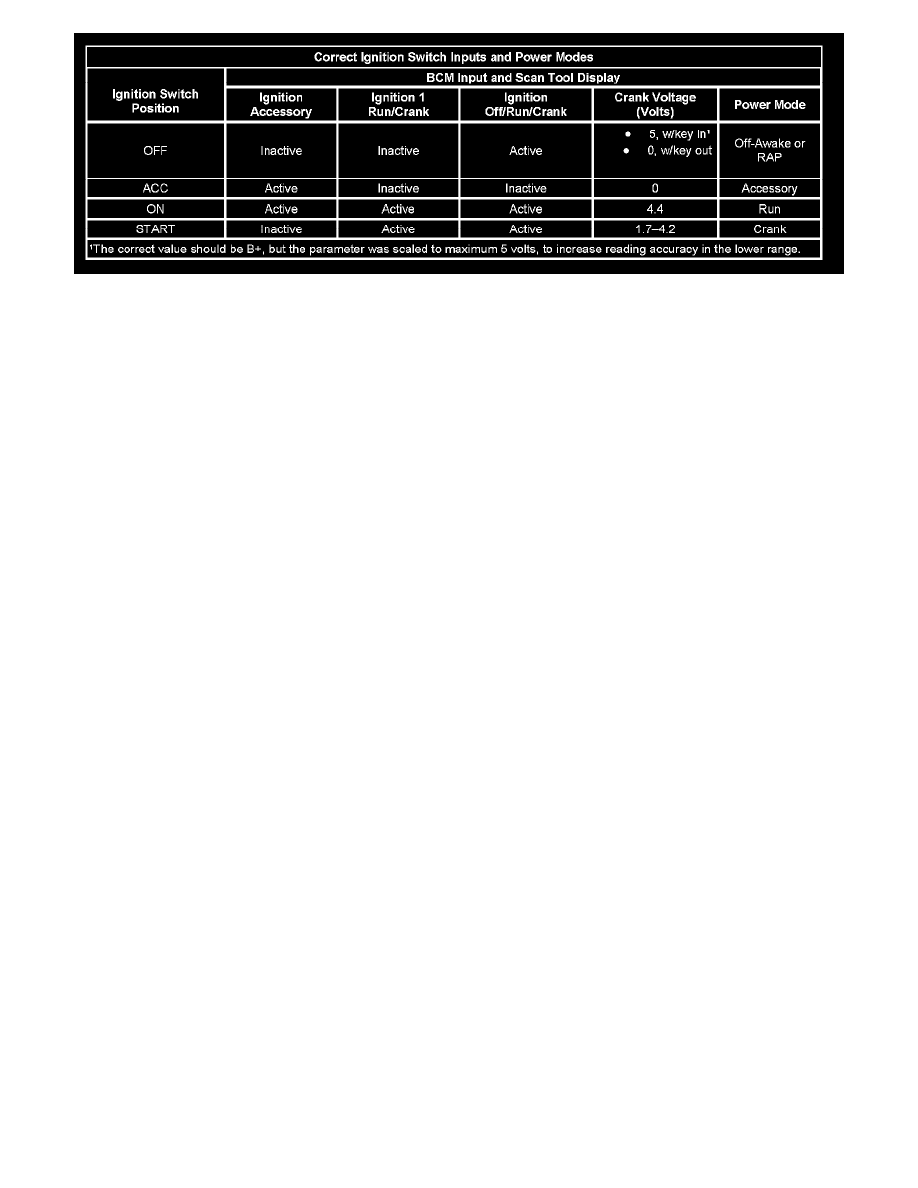
Correct Ignition Switch Inputs And Power Modes
The body control module (BCM) monitors the ignition inputs Ignition Off/Run/Crank, Ignition 1 Run/Crank and the Ignition Accessory signals
supplied from the ignition switch. The BCM uses the sequence that the signals appear, their voltage levels and the engine run flag (ERF) status to
determine the power mode. Battery voltage is supplied to the ignition switch by the IGN TRANSD fuse. The ignition key resistor signal from the
BCM provides a 5-volt supply voltage to the ignition switch. The table below shows the correct ignition switch inputs and power modes.
TEST
