
Colorado 4WD L5-3.5L VIN 6 (2005)
TOOLS REQUIRED
J 38125 Terminal Repair Kit
TERMINAL REMOVAL PROCEDURE
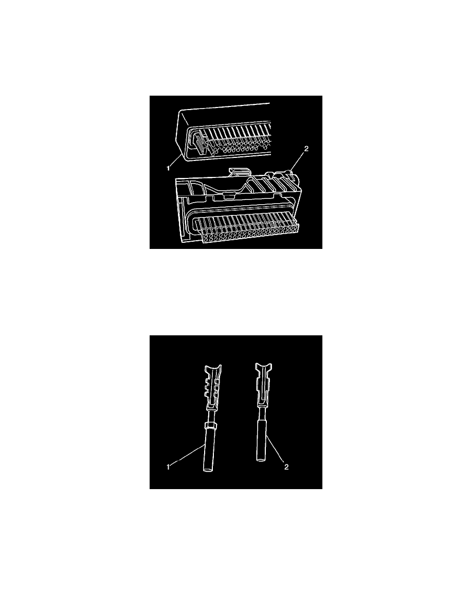
There are 2 styles of Micro-Pack 100W connectors. These connectors are very similar but use different terminals and have some minor physical
differences also.
The first connector design of the Micro-Pack 100W (1) has a white connector interface that holds the terminals. The second design of the Micro-Pack
100W (2) has a gray interface to hold the terminals. Also, the first design has terminal cavities that are further apart (3 mm centerline) and offset from
the other row of terminal cavities in the connector. The second design has terminals cavities that are closer together (2.54 mm centerline) and aligned
vertically. One other way to identify the second design is the thin strip of material that runs along the outside of the cavities.
IMPORTANT: There are 2 styles of Micro-Pack 100W terminals which are very similar. Ensure that you have the correct terminal before crimping
the new terminal to the wire. The first design connector uses the longer terminal (1) that has a raised area in front of the recess in the terminal. The
second design connector uses the shorter terminal without the raised area.
Follow the steps below in order to remove terminals from Micro-Pack 100W connectors. Some Micro-Pack 100W connector disassembly procedures
will vary. Use this procedure as a guide.
1. Disconnect the connector from the component.