
Colorado 4WD L5-3.7L (2007)
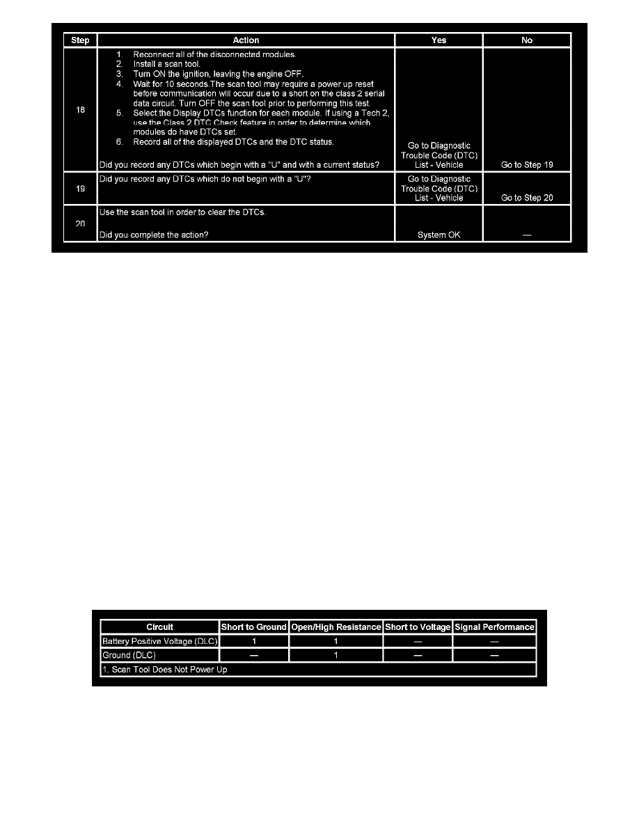
Step 18 - Step 20
The numbers below refer to the step numbers on the diagnostic table.
3. A partial malfunction in the class 2 serial data circuit uses a different procedure from a total malfunction of the class 2 serial data circuit. The
following modules communicate on the class 2 serial data circuit:
-
The body control module (BCM)
-
The electronic brake control module (EBCM)
-
The inflatable restraint sensing and diagnostic module (SDM)
-
The instrument panel cluster (IPC)
-
The powertrain control module (PCM)
-
The radio
-
The rear seat entertainment (RSE) assembly
-
The transfer case shift control module (TCSCM)
-
The vehicle communication interface module (VCIM)
4. The following DTCs may be retrieved with a history status, but are not the cause of the present condition.
-
U1300
-
U1301
-
U1305
7. A state of health DTC with a history status may be present along with a U1000 or U1255 code having a current status. This indicates that the
malfunction occurred when the ignition was ON.
8. Data link connector terminals 2 and 5 provide the connection to the class 2 serial data circuit and the signal ground circuit respectively.
18. If there are no current DTCs that begin with a "U", the communication malfunction has been repaired.
19. The communication malfunction may have prevented diagnosis of the customer complaint.
Scan Tool Does Not Power Up
SCAN TOOL DOES NOT POWER UP
DIAGNOSTIC FAULT INFORMATION
Perform the Diagnostic System Check - Vehicle prior to using this diagnostic procedure. See: Testing and Inspection/Initial Inspection and Diagnostic
Overview/Diagnostic Starting Point - Vehicle
CIRCUIT/SYSTEM DESCRIPTION
The data link connector (DLC) is a standardized 16 cavity connector. Connector design and location is dictated by an industry wide standard, and is
required to provide the following:
-
Scan tool power battery positive voltage at terminal 16
-
Scan tool power ground at terminal 4