
Colorado 4WD L5-3.7L (2007)
5. IMPORTANT: On connectors with more than one terminal the service loop may not be large enough to remove the terminal and crimp on a new
one. If the terminal wire does not have a large enough service loop for removal, cut the wire 5 cm (2 in) behind the connector before removal.
Grasp the wire at the back of the connector body and gently push the terminal out the front of the connector body.
TERMINAL REPAIR
1. If the wire needed to be cut in order to remove the terminal, gently push a small length of the same size wire through the back of the connector
cavity until there is enough wire exposed in order to crimp on a new terminal. If the wire was not cut, cut the existing wire as close to the old
terminal as possible.
2. Strip 5 mm (3/16 in) of insulation from the wire.
3. Crimp a new terminal to the wire.
4. Solder the crimp with rosin core solder.
TERMINAL INSTALLATION
1. Align the terminal and pull the wire from the back of the connector in order to seat the terminal.
2. If necessary, cut the new wire to proper length and splice with existing circuit. Refer to Splicing Copper Wire Using Splice Sleeves.
3. If the connector is outside of the passenger compartment, apply dielectric grease to the connector.
4. Install the TPA, CPA, and/or the secondary locks.
Delphi Connectors (Push To Seat)
DELPHI CONNECTORS (PUSH TO SEAT)
TOOLS REQUIRED
J-38125 Terminal Repair Kit
TERMINAL REMOVAL
Follow the steps below in order to repair push to seat connectors.
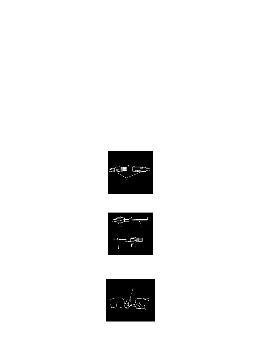
1. Remove the terminal position assurance (TPA) device, the connector position assurance (CPA) device, and/or the secondary lock.
2. Separate the connector halves (1).
3. Use the proper pick or removal tool (1) in order to release the terminal. See the release tool cross reference in the Reference Guide of the J-38125
to ensure that the correct release tool is used.
4. Gently pull the cable and the terminal (2) out of the back of the connector.