
Colorado 4WD V8-5.3L (2010)
Ignition Switch Lock Cylinder: Procedures
Key and Lock Cylinder Coding
Door Lock Cylinder
The front side door lock cylinder uses 8 of the 10 key cut positions, 3-10 when counting from the key head. The tumbler orientations alternate in adjacent
locations from side to side with 4 tumblers on each side.
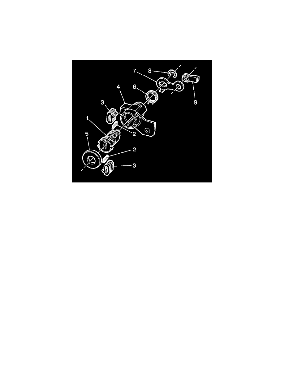
Note: The front side door lock cylinder tumblers (3) are not self retaining and must be held in place if the key is not fully inserted in the lock
cylinder, or until the lock cylinder (1) is assembled into the case assembly (4).
1. Hold the uncoded cylinder (1) positioned so the side of rotational stop lug is facing downward, as shown.
2. Insert one tumbler spring (2) each into the 4 holes from the upper side.
Note: The GM codebook number is not the same value as those stamped on the tumblers, i.e. GM number 1 = tumbler number 4, GM number 2 =
tumbler number 3, GM number 3 = tumbler number 2, and GM number 4 = tumbler number 1.
3. The first tumbler to be loaded will be key cut position number 3, the third number in the key code.
4. Determine the cut depth at this position and install the corresponding tumbler (3) into the tumbler slot nearest the front of the rotor-CP.
5. In the same manner, determine the cut depth and corresponding tumbler and install the 3 remaining tumblers (3) into the tumbler slots located at
key cut positions 5, 7, and 9.
6. Check for correct loading by holding the tumblers (3) in position and fully inserting the matching key into the rotor. All the tumblers should be
flush with the outside diameter of the rotor.
7. Rotate the cylinder (1) so that the side with the rotational stop lug is facing upward and then remove the matching key. Remember the tumblers (3)
are not self retaining and must be held in place.
8. Insert one tumbler spring (2) each into the 4 tumbler spring holes.
9. The first tumbler to be loaded will be key cut position number 4. Determine the cut depth at this position and install the corresponding tumbler (3)
into the tumbler slot nearest the front of the rotor-CP.
10. In the same manner, determine the cut depth and corresponding tumbler and install the 3 remaining tumblers (3) into the tumbler slots located at
key cut positions 6, 8, and 10.
11. Check for correct loading by holding the tumblers (3) in position and fully inserting the matching key into the rotor (1). All tumblers should be
flush with the outside diameter of the rotor (1).
12. Lightly lubricate tumbler (3) and cylinder (1) surfaces using the lubrication provided.
13. With the matching key fully inserted into coded cylinder, install the coded cylinder into the case (4) fully. Make sure the cylinder is stopped at
approximately 60 degrees when rotated with the key, approximately 120 degrees total.
14. Remove the key, the cylinder stays in the case, and install the lock cylinder cap (5) on the case (4). Crimp the side edge of the lock cylinder cap (5)
around the case depressions (2 places).
15. Hold the cylinder assembly so the key opening is facing down (6 o'clock), and the cylinder cut out is facing you, so the tumblers are visible.
16. Keep the cylinder assembly in the same orientation as above, key opening at 6 o'clock, rotor top at 12 o'clock. The return spring consists of a lower
and upper spring tab. Locate the lower spring tab to the left side of the cylinder tab. This cylinder tab is located at the 12 o'clock position and