
Corsica L4-2.2L VIN 4 (1995)
Steering Gear: Service and Repair
Removal/Installation
NOTICE: The wheels of the vehicle must be straight ahead and the ignition switch in the "LOCK" position before disconnecting the flange and coupling
assembly from the steering column or the rack and pinion steering gear. Failure to do so may cause the supplemental inflatable restraint (SIR) coil
assembly to become off centered, which will damage the SIR coil assembly.
REMOVE OR DISCONNECT
1. Left sound insulator.
2. Upper pinch bolt on coupling assembly.
3. Line retainer (if applicable).
4. Power brake away from cowl wall, leaving master cylinder attached.
5. Raise vehicle.
6. Left front tire and wheel assembly.
7. Tie rod ends from struts using J 24319-01.
8. Lower vehicle.
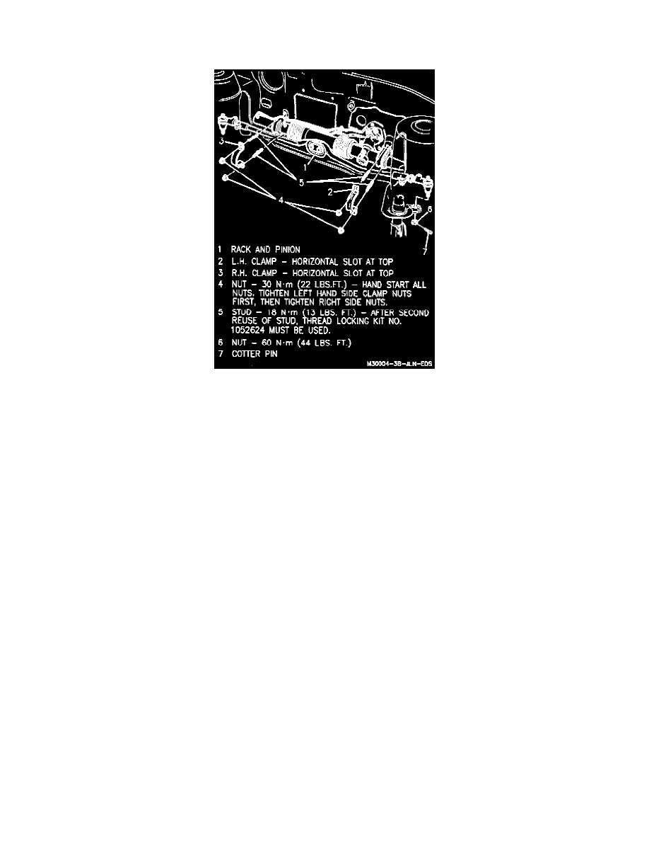
9. Left and right mounting clamps.
10. Gear inlet and outlet pipes from rack and pinion steering gear.
11. Move rack and pinion assembly forward and remove lower pinch bolt from flange on coupling assembly.
12. Coupling from rack and pinion.
13. Dash seal from rack and pinion.
14. Rack and pinion through left wheel opening.
Important:
If studs were removed with mounting clamps, reinstall studs into cowl panel and tighten until the studs are fully seated against the dash panel. The
torque should not exceed 20 Nm (15 lbs. ft.). After second reuse of stud, thread locking kit GM P/N 1052624 or equivalent must be used.
INSTALL OR CONNECT
1. Rack and pinion through left wheel opening.
2. Dash seal on rack and pinion assembly.
3. Move rack and pinion assembly forward and install coupling on rack and pinion.
4. Flange and coupling lower pinch bolt.
Tighten
Lower pinch bolt to 41 Nm (30 lbs. ft.).
5. Gear inlet and outlet pipes to rack and pinion steering gear.
Tighten