
Corsica V6-3100 3.1L MFI VIN M (1994)
Oxygen Sensor: Description and Operation
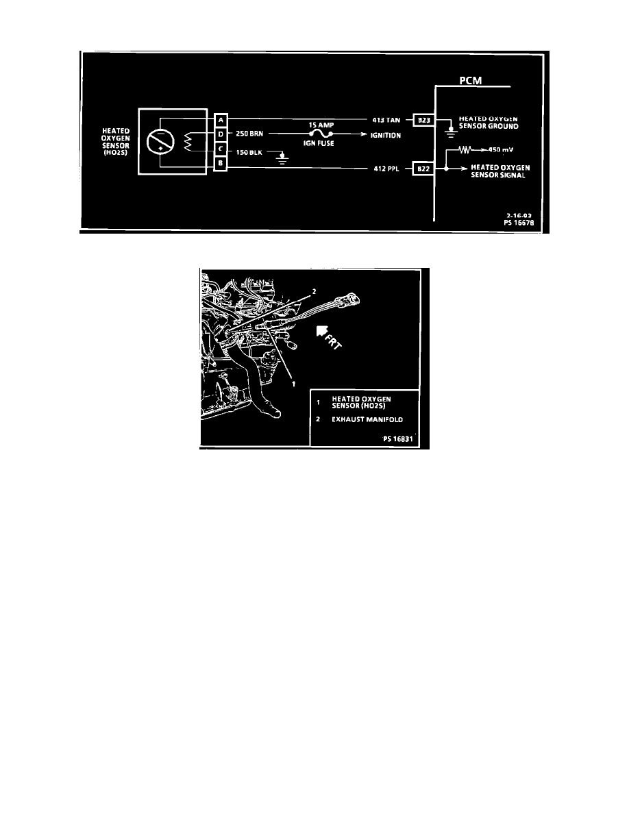
Oxygen Sensor Circuit Diagram
Oxygen Sensor Installation
PURPOSE AND LOCATION
The oxygen sensor, installed in the exhaust manifold, monitors exhaust gas oxygen content and produce a voltage output. The PCM uses this voltage
value to calculate the percentage of oxygen in the exhaust gas and adjusts the fuel injector pulse width to mauntain the correct air/fuel ratio.
CONSTRUCTION AND OPERATION
The sensor consists of a hollow Zirconia element with a Platinum coating on its inside and outside surfaces. The open end of the element is exposed to
the atmosphere and its surface is connected to the ECU, while the closed end protrudes into the exhaust stream and its surface is connected to ground.
The oxygen sensor element only reacts efficiently with oxygen if the temperature of the element is around 300~C (575~F) or hotter. When there is a
difference in the amount of oxygen reacting with the inner and outer surfaces, a voltage potential is generated. The normal operating voltage range is
approximately 0.1-1.0V. Voltage increases when the concentration of oxygen in the exhaust is low (rich air/fuel ratio) and decreases when the
concentration is high (lean air/fuel ratio).
A heating element is built into the sensor to help bring it up to operating temperature more quickly and to maintain it at operating temperture during
periods of decelerating or prolonged idle, when it would otherwise cool off.