
Corsica V6-3100 3.1L MFI VIN M (1994)
Crankshaft Position Sensor: Description and Operation
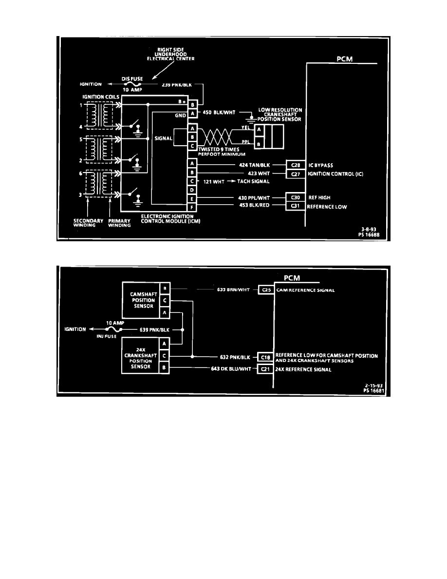
Ignition Control Module Circuit Diagram
Cam And Crankshaft Sensor Circuit Diagram
GENERAL INFORMATION
This engine uses two crankshaft position sensors. One sensor, mounted on the side of the engine block (3X cankshaft sensor), and another (24X
sensor) mounted on the front of the engine behind the harmonic ballancer.
PURPOSE
The 3X crankshaft sensor provides crankshaft position and engine speed information to the ignition module and control unit. The signal indicates
the exact position of the crankshaft once each revolution, and the relative position every 60° thereafter. This signal is used as a reference for fuel
injection, ignition timing, and engine speed calculations.
The 24X crankshaft sensor produces a signal every 15° of crankshaft rotation for ignition timing calculations.