
Corsica V6-3100 3.1L MFI VIN M (1994)
Ignition Control Module: Description and Operation
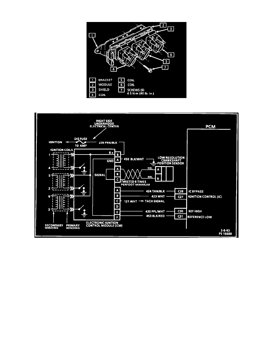
Typical Ignition Module Assembly
Ignition Control Module Circuit Diagram
PURPOSE
This DIS module monitors the crank sensor signals and based on these signals sends a reference signal to the PCM so that correct spark and fuel
injector control can be maintained during all driving conditions.
OPERATION
During cranking, the DIS module monitors the "sync pulse" to begin the ignition firing sequence and below 400 rpm the module controls spark
advance by triggering each of the three coils at a pre-determined interval based on engine speed only. Above 400 rpm the PCM controls the spark
timing through the module (EST), and compensates for all driving conditions. The DIS module must receive a "sync pulse" and then a crank signal
in that order to enable the engine to start. The DIS module is not repairable. When a module is replaced, the ignition coils must be transferred to
the new module.