
Corvette V8-5.7L VIN G (1997)
Diagnostic Tables provide a procedure to follow that will locate the condition in a circuit causing a malfunction. If your own knowledge of the system
has not produced a quick fix, follow the Diagnostic Table. All procedures are based on symptoms to assist in locating the condition as fast as possible.
Diagnostic Tables should exist for all possible (realistic) symptoms and Diagnostic Trouble Codes (DTCs).
DTC Communication System
^
Electrical Schematics
^
Schematic Reference Table
^
Schematic Icon Table
^
Component Location Table
^
Component Location Views
^
Connector End Views
^
Scan Tool
^
Diagnostic Support Information
Using these elements together will make electrical troubleshooting faster and easier.
Electrical Schematics
Wiring System
The wiring schematic is the cornerstone of electrical diagnosis. Schematics break the entire electrical system down into individual circuits, showing the
electrical current paths when a circuit is operating properly. Wiring which is not part of the circuit of interest is referenced to another page, where the
circuit is shown complete. Schematics use a top (power) to bottom (ground) sequence to present electrical information.
IMPORTANT: It is important to realize that no attempt is made on the schematic to represent components and wiring as they physically appear on the
vehicle. For example, a 4-foot length of wire is treated no differently in a schematic from one which is only a few inches long.
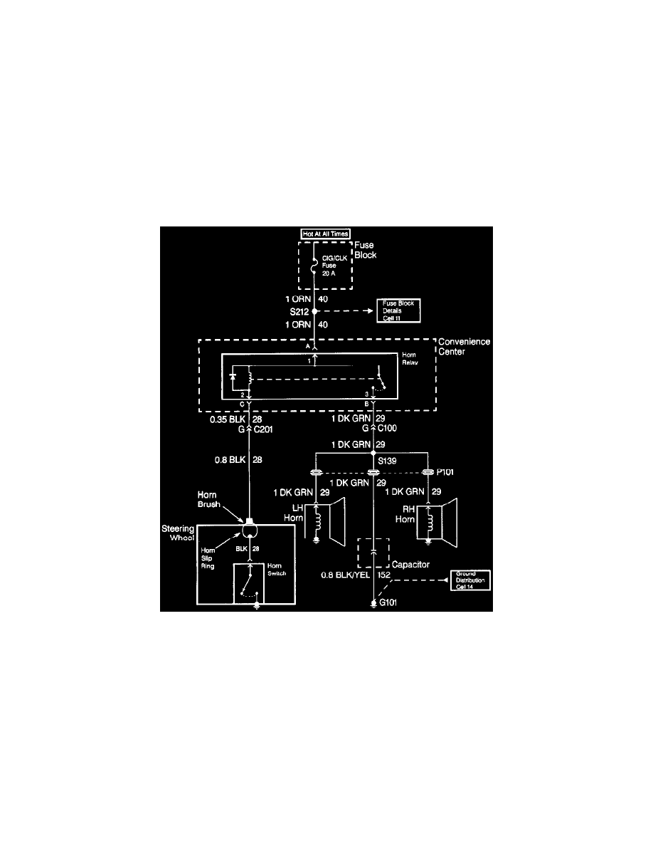
When diagnosing a horn problem, the technician would reference the horn section. The following schematic is a typical example of what would be found
in a horn section, along with the included text.
Voltage is applied to the Horn Relay at all times. When the relay coil is grounded by closing the Horn Switch, the relay contacts close. When the relay
contacts are closed, both the LH and RH Horns are energized.
Non-DTC Communication System