
Corvette V8-5.7L VIN G (1997)
Throttle Position Sensor: Description and Operation
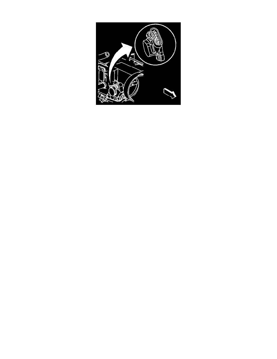
DESCRIPTION
The Throttle Position (TP) sensor is mounted on the throttle body assembly. The sensor is actually two individual Throttle Position sensors within one
housing. Two separate signal, ground and 5 volt reference circuits are used to connect the TP sensor assembly and the Throttle Actuator Control
(TAC) Module. The two sensors have opposite functionality.
OPERATION
The TP sensor 1 signal voltage increases as the throttle opens, from below 1.1 volts at 0% throttle to above 3.7 volts at 100% throttle. The TP sensor 2
signal voltage decreases from above 3.9 volts at 0% throttle to below 1.2 volts at 100% throttle. Note also that the signal circuit for TP Sensor 1 is
pulled up to 5 volts and that the signal circuit for TP Sensor 2 is pulled to ground within the TAC Module. The TAC module converts these different
signals to a common scale and continuously compares them to each other to verify proper system operation.
DIAGNOSIS
When the PCM detects a malfunction with the TP sensor circuits, the following DTCs will set:
^
DTC P1120 Throttle Position TP Sensor 1 Circuit.
^
DTC P1220 Throttle Position TP Sensor 2 Circuit.
^
DTC P1221 Throttle Position TP Sensors 1, 2 Performance.