
Corvette V8-5.7L VIN G (1997)
Camshaft Position Sensor: Description and Operation
DESCRIPTION
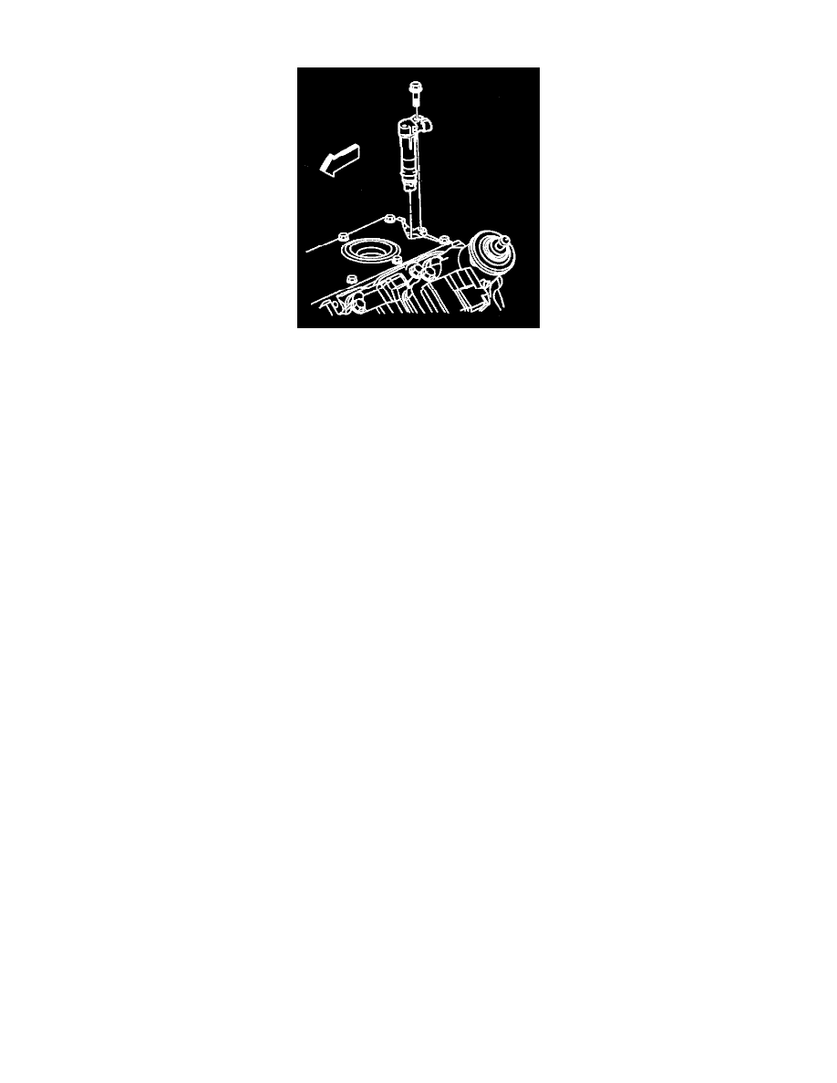
The Camshaft Position (CMP) sensor is mounted through the top of the engine block at the rear of the valley cover. The Camshaft Position sensor
works in conjunction with a 1X reluctor wheel on the camshaft. The reluctor wheel is inside the engine immediately in front of the rear cam bearing.
The PCM provides a 12 volt power supply to the CMP sensor as well as a ground and a signal circuit.
OPERATION
The Camshaft Position sensor is used to determine whether a cylinder is on a firing or exhaust stroke. As the camshaft rotates, the reluctor wheel
interrupts a magnetic field produced by a magnet within the sensor. The sensors internal circuitry detects this and produces a signal which is read by
the PCM. The PCM uses this 1X signal in combination with the Crankshaft Position Sensor 24X signal to determine crankshaft position and stroke.
This diagnostic for the Camshaft Position sensor checks for a loss of Camshaft Position sensor signal.
CIRCUIT MALFUNCTIONS
The PCM also monitors the CMP sensor signal circuit for malfunctions. The following DTCs set when the PCM detects a CMP sensor that is out of
the normal operating range.
^
DTC P0341 Camshaft Position Sensor (CMP) Circuit Performance.
^
DTC P0342 Camshaft Position Sensor (CMP) Circuit Low Voltage.
^
DTC P0343 Camshaft Position Sensor (CMP) Circuit High Voltage.