
Corvette V8-5.7L VIN G (1997)
Description
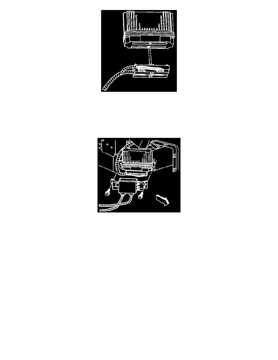
7. Disconnect the PCM electrical harness connectors.
8. Loosen but do not remove the PCM rear retaining fastener. Use the rear retaining fastener as an anchor for the outer bracket.
9. Remove the front retaining fastener from the PCM.
10. Reposition the PCM outer bracket.
11. Remove the PCM from the bracket and the vehicle.
Description
INSTALLATION PROCEDURE
1. Install the PCM to the PCM rear bracket.
2. Position the PCM front bracket.
3. Install the PCM front retaining fastener. Tighten the PCM retaining fasteners to 2.2 Nm (17 lb. in).
4. Connect the electrical connectors to the PCM.
5. Connect the electrical connectors to the TAC module.
6. Align the hole in the rear mounting tab of the TAC module to the corresponding hole in the PCM mounting bracket. Position the TAC module
below the rear mounting tab for greater clearance in order to install the rear retaining fastener.
7. Install the TAC module rear retaining fastener.
8. Align the front mounting holes of the TAC module.
9. Install the TAC module front retaining fasteners. Tighten the TAC module retaining fasteners to 1.9 Nm (17 lb. in).
10. Install the wheelhouse filler panel.
11. Install the right front tire and wheel assembly.
12. Lower the vehicle.
13. Program the EEPROM if a new PCM is being installed.
EEPROM PROGRAMMING
Setup
1. Ensure that the following conditions have been met:
^
The battery is fully charged.
^
The ignition is ON.
^
The scan tool cable connection at the DLC is secure.