
Corvette V8-5.7L VIN G (1997)
If necessary, check the "Claim History" in the "Summary" section in the GM Vehicle Inquiry System (GMVIS) to determine whether Customer
Satisfaction Campaign (CSC) 01044 or Technical Service Bulletin (TSB) 01-02-35-008 has been performed on a vehicle. DO NOT use the
"Required Field Action" section to determine whether Customer Satisfaction Campaign 01044 has been performed. All vehicles involved in that
Campaign were listed as closed when the campaign was cancelled. If either has been performed, labor operation V0743 (CSC 01044) or N8505
(TSB 01-02-35-008) will be listed.
After determining the required repairs for the vehicle you are working on, proceed to the appropriate Service Procedures in this bulletin for
instructions.
Important:
If the vehicle requires the installation of a "Wire/Relay Kit", that must be done first, followed by the "Reprogram" followed by the "Functional
Test". If the vehicle does not require the "Wire/Relay Kit," then you should first perform the "Reprogram" followed by the "Functional Test."
Remember, you must complete "all" repairs listed for the vehicle being worked on in order to complete this recall.
Installing Wire and Relay Kit, P/N 88952428 (Procedure 1B)
This procedure should ONLY be done if the vehicle you are working on has NOT had Customer Satisfaction Campaign (CSC) 01044 or Technical
Service Bulletin (TSB) 01-02-35-008 performed. See the information above.
1.
Turn the steering wheel so that the vehicle's front wheels are pointing straight ahead.
2.
Turn the ignition switch to the OFF position.
3.
Open the hood and disconnect the negative battery cable.
4.
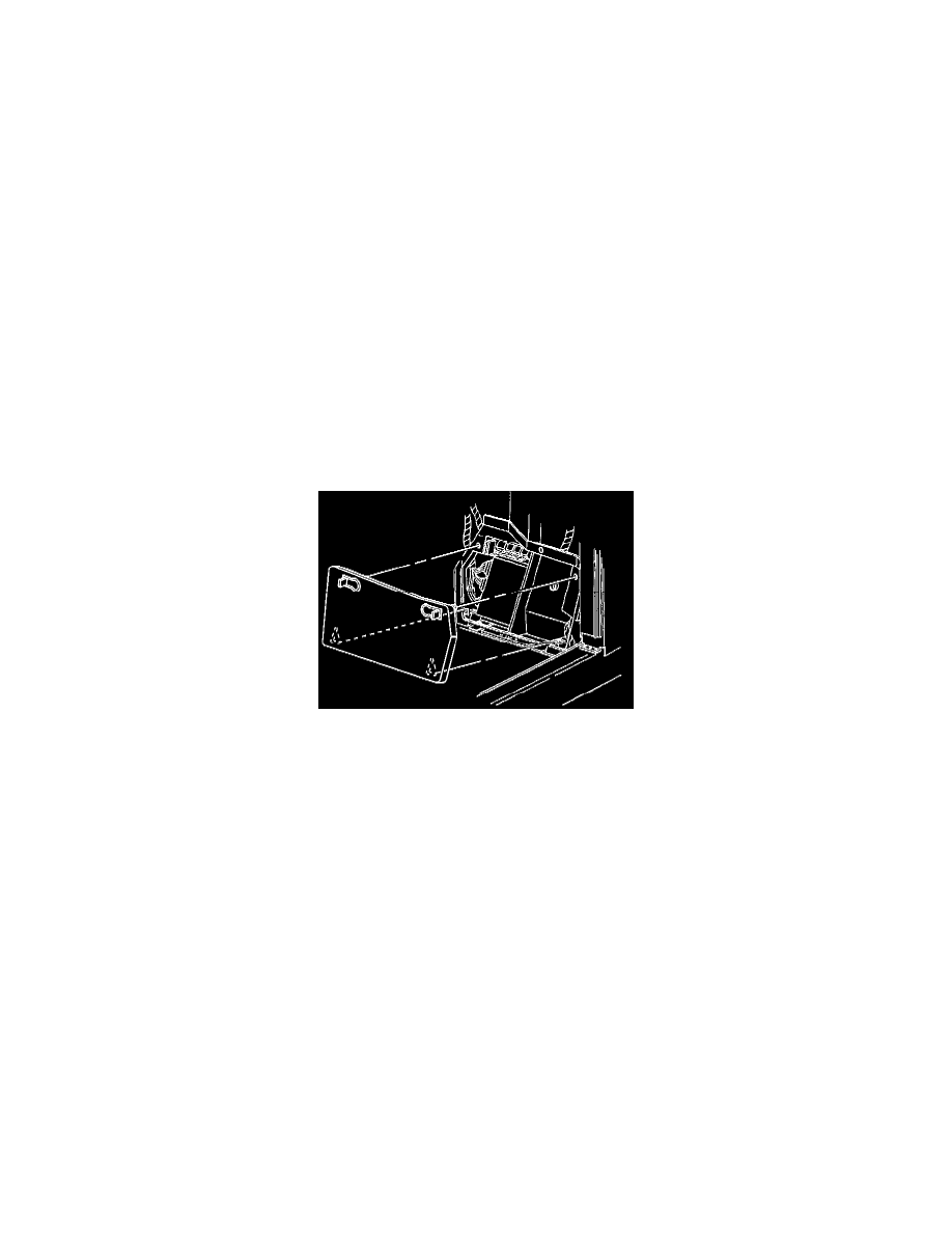
Disengage the upper latches on the front kick-up panel on the passenger side.
5.
Lift the kick-up panel's lower edge out of the slots in the relay bracket.
Important:
The Electric Column Lock (ECL) relay described in the next step can be identified by the four wires that connect to it. Prior to the
modification being done, there should be two ORANGE wires, one DARK GREEN, and one WHITE wire. If there is also a purple wire (a
total of five wires), then the Wire and Relay Kit has already been installed and you should proceed to the section titled "Service
Reprogramming."
6.
Locate the ECL relay, which is above the body control module (BCM).
7.
Remove the connector position assurance (CPA) clip from the back of the ECL relay connector.
8.
Remove the ECL relay harness from the backside of the relay assembly.
Important:
The relay being removed in the next step is a single pole, single throw design. With the wiring modifications being made in the next steps, a
single pole, double throw relay is required. Only the new relay included with the jumper harness can be used once the wiring modifications
have been made.
9.
Remove the ECL relay from the connector and discard the relay.
10.
Using the appropriate terminal release tool, remove the ORANGE wire from position C1 on the ECL relay connector.
11.
Using the appropriate terminal release tool, remove the WHITE wire from position A2 on the ECL relay connector.