
Corvette V8-5.7L VIN G (1997)
Note:
When installing the cam orientation plate in the next step, a NEW retaining ring must be used. Do not reuse the original retaining ring.
^
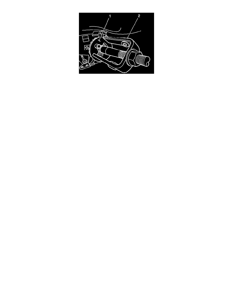
J 23653-SIR and J 42137 MUST be used when installing the orientation plate and retaining ring in the next step. Failure to use these tools
may result in damage to the cam orientation plate, retaining ring or steering column components.
29.
Using J 23653-SIR and J 42137 (1), install the cam orientation plate and the new retaining ring included in the recall kit. The cam orientation plate
replaces the lock plate removed in the previous step.
30.
Position the SIR coil on the steering column and install the snap ring.
313
Disconnect the electrical connector from the ECL, located on the right lower side of the steering column.
32.
Attach the NEW relay (1) and harness, included in the kit, to the left IP brace as shown and secure with plastic tie straps.
33.
Route the NEW relay harness over the knee bolster.
Important:
The connectors on the NEW relay harness are specific and MUST be connected correctly in the next steps. When connected, the new
connection becomes J165/P165.
34.
Connect one end of the NEW relay harness into the connector on the ECL. Connect the other end on the NEW relay harness into the connector
that was disconnected from the ECL in Step 31.
35.
Install the upper steering column cover and install the attaching screw.
Tighten
Tighten the screw to 1.9 N.m (17 lb in).
36.
Install the lower steering column and attaching screws.
Tighten
Tighten the screws to 4 N.m (35 lb in).
37.
If equipped, connect the electrical connector to the inside air temperature sensor located on the knee bolster trim panel.
38.
Install the knee bolster trim panel and press firmly to engage the locking tabs.
39.
Install the lower retaining screws and the screw located behind the combination fog lamp/trunk release switch, and the inside air temperature
sensor grill.
Tighten
Tighten the screws to 1.8 N.m (16 lb in).
40.
Connect the electrical connector to the combination fog lamp/trunk release switch and install the assembly into the opening in the IP. Press firmly
to secure. Repeat this step on the inside air temperature sensor grill.