
Corvette V8-5.7L VIN G (1997)
Cross-Member: Service and Repair
Front Suspension
Removal Procedure
^
Tools Required
-
J 33432-A Transverse Leaf Spring Compressor and Adaptors
-
J 42188 Ball Joint Separator
-
J 41803 Engine Support Fixture
-
Or Equivalents
1. Disconnect the negative battery cable.
Caution Disconnect the negative battery cable under the following circumstances:
-
When installing an electrical unit.
-
When a tool or equipment could easily come into contact with "live" exposed electrical terminals.
Failure to disconnect the negative battery terminal may result in personal injury or damage to the vehicle's components. Turn OFF the vehicle
ignition, unless instructed otherwise.
2. Remove the generator from the accessory mounting bracket.
3. Install J 41803 and support the engine.
4. Raise and support the vehicle.
5. Remove the tire and wheel assemblies.
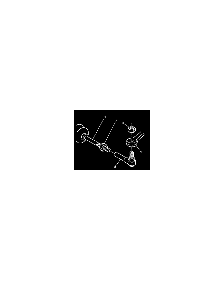
6. Loosen the steering linkage outer tie rod nuts (3). Do not remove the nuts.
7. Install J 42188 on the left steering linkage outer tie rod end.
8. Separate the left steering linkage outer tie rod (5) from the steering knuckle (4).
9. Remove J 42188 and the steering linkage tie rod nut from the left steering linkage outer tie rod.
10. Install J 42188 on the right steering linkage outer tie rod end.
11. Separate the right steering linkage outer tie rod from the steering knuckle.
12. Remove J 42188 and the steering linkage tie rod nut from the right steering linkage outer tie rod.
13. If equipped disconnect the Real Time Dampening (RTD) sensor from the upper control arms.
14. Support the lower control arms with jack stands.
15. Disconnect the stabilizer bar links from the lower control arms.