
Corvette V8-5.7L VIN G (1997)
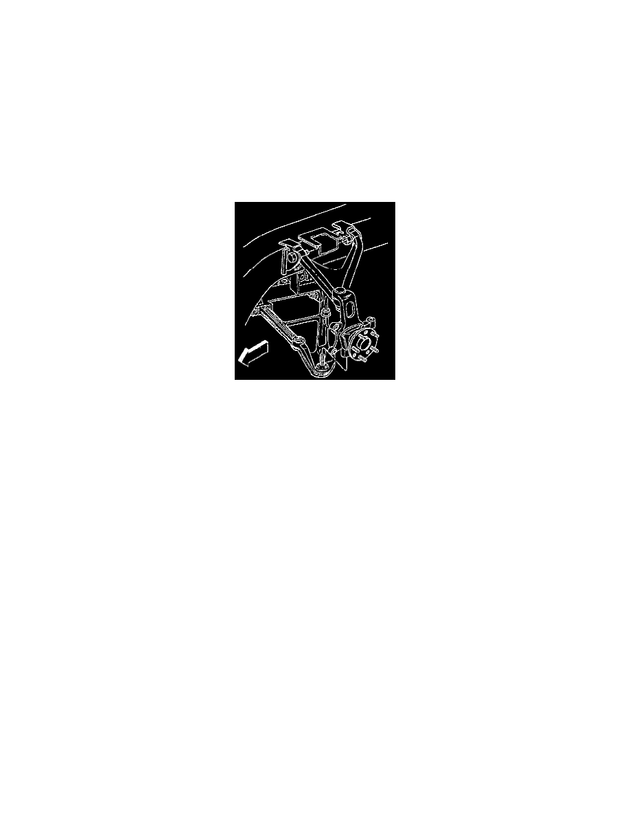
26. Support the right hand lower control arm with a jack stand.
27. Remove J 42188 and the lower bail joint stud nuts.
28. Remove the jack stands from the lower control arms.
29. Disconnect the lower control arms from the rear suspension knuckles.
30. Pull back on the steering knuckles until drive axle clears the differential. Refer to Drive Axle Replacement in Drive Axle. See: Transmission and
Drivetrain/Drive Axles, Bearings and Joints/Axle Shaft Assembly/Service and Repair
31. Support the drive axles and the rear suspension knuckles.
32. Disconnect all the electrical connectors from the crossmember.
33. Disconnect the brake lines from the crossmember.
34. Support the transaxle under the transmission pan with a trans jack.
35. Remove the rear crossmember mounting nuts.
36. Remove the crossmember from the vehicle.
Installation Procedure
1. Install the crossmember into vehicle.
-
Align the crossmember dowel pins to the holes in frame rails.
-
Align the transaxle mount studs into the crossmember.
2. Connect all electrical connectors on the crossmember.
3. Connect the brake lines onto the crossmember.
4. Install new rear suspension crossmember mounting nuts.
-
Tighten the new rear crossmember mounting bolts to 110 Nm (81 ft. lbs.).
Notice: Always use the correct fastener In the proper location. When you replace a fastener, use ONLY the exact part number for that
application. The manufacturer will call out those fasteners that require a replacement after removal. The manufacturer will also call out the
fasteners that require thread lockers or thread sealant. UNLESS OTHERWISE SPECIFIED, do not use supplemental coatings (paints, greases,
or other corrosion Inhibitors) on threaded fasteners or fastener joint interfaces. Generally, such coatings adversely affect the fastener torque
and joint clamping force, and may damage the fastener. When you install fasteners, use the correct tightening sequence and specifications.
Following these instructions can help you avoid damage to parts and system.
5. Remove the trans jack from the crossmember.
6. Install the transaxle mount lower nuts. Refer to A/T Mount Replacement.
7. Install the inner cv joints into the differential. Refer to Drive Axle Replacement in Drive Axle. See: Transmission and Drivetrain/Drive Axles,
Bearings and Joints/Axle Shaft Assembly/Service and Repair
8. Install the rear suspension knuckles onto the lower control arms.
9. Support the lower control arms with jack stands.
a. Tighten the ball joint stud nut to 20 Nm (15 ft. lbs.) to seat the ball joint stud.
b. Turn the nut an additional 3 1/2 flats.
c. Check the ball joint stud nut for a minimum final torque of 55 Nm (41 ft. lbs.).