
Corvette V8-6.0L VIN U (2005)
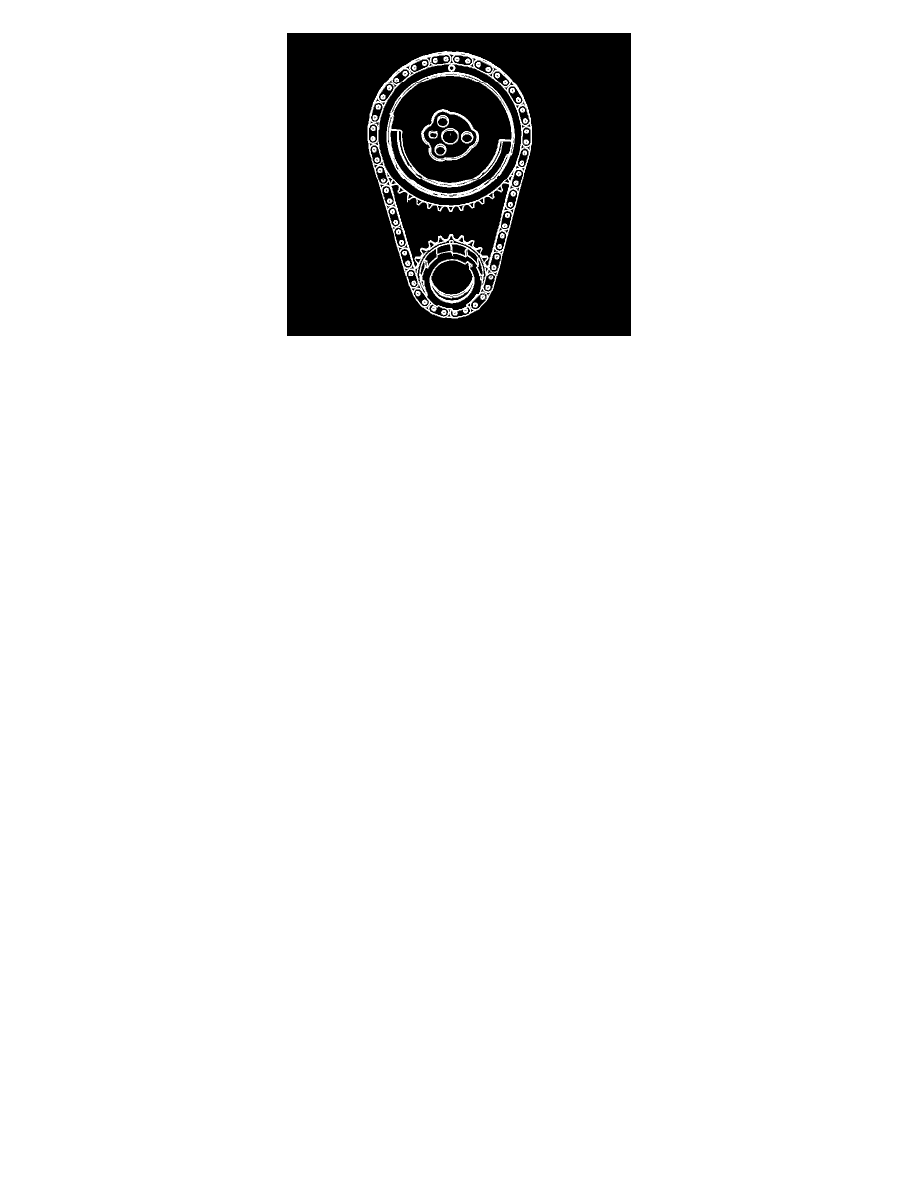
6. Rotate the crankshaft until number one piston is at top dead center of compression stroke. In this position, cylinder number one rocker arms will be
off lobe lift, and the crankshaft sprocket key will be at the 1:30 position. The camshaft and crankshaft sprocket alignment marks will be in the 12
o'clock positions. If viewing from the rear of the engine, the additional crankshaft pilot hole, non-threaded, will be in the 10:30 position. The
engine firing order is 1, 8, 7, 2, 6, 5, 4, 3.Cylinders 1, 3, 5 and 7 are left bank. Cylinders 2, 4, 6, and 8 are right bank.
7. Notice: Refer to Fastener Notice in Service Precautions.
With the engine in the number one firing position, tighten the following valve rocker arm bolts:
^
Tighten exhaust valve rocker arm bolts 1, 2, 7, and 8 to 30 Nm (22 ft. lbs.).
^
Tighten intake valve rocker arm bolts 1, 3, 4, and 5 to 30 Nm (22 ft. lbs.).
8. Rotate the crankshaft 360 degrees.
9. Tighten the following valve rocker arm bolts:
^
Tighten exhaust valve rocker arm bolts 3, 4, 5, and 6 to 30 Nm (22 ft. lbs.).
^
Tighten intake valve rocker arm bolts 2, 6, 7, and 8 to 30 Nm (22 ft. lbs.).
10. Install the valve rocker arm covers.