
Corvette V8-60L VIN U (2005) - Power Window Switch Diagram
1. Align the terminal and pull the wire from the back of the connector in order to seat the terminal.
2. If necessary, cut the new wire to proper length and splice with existing circuit. Refer to Splicing Copper Wire Using Splice Sleeves .
3. If the connector is outside of the passenger compartment, apply dielectric grease to the connector.
4. Install the TPA, CPA and/or the secondary locks.
Micro .64 Connectors
MICRO .64 CONNECTORS
TOOLS REQUIRED
J 38125-D Terminal Repair Kit
REMOVAL PROCEDURE
Follow the steps below in order to remove terminals from Micro 64 connectors.
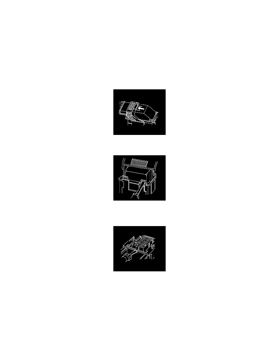
1. Locate the lever lock on the wire dress cover. While depressing the lock, pull the lever over and past the lock.
2. Disconnect the connector from the component.
3. Locate the dress cover locking tabs at the front of the connector. Using a small flat-blade tool push down on one of the locking tabs and pull the
cover up until the dress cover releases. Repeat this procedure for the other locking tab.
4. Once the front 2 locks are unlocked, lift the front of the dress cover and pull it forward.
5. If the connector has a nose piece, use a small flat-blade tool to remove the nose piece by inserting the blade into the slot on the front of the
connector and prying up on the nose piece.
IMPORTANT: Always use care when removing a terminal position assurance (TPA) in order to avoid damaging it.