
Corvette V8-6.2L (2008)
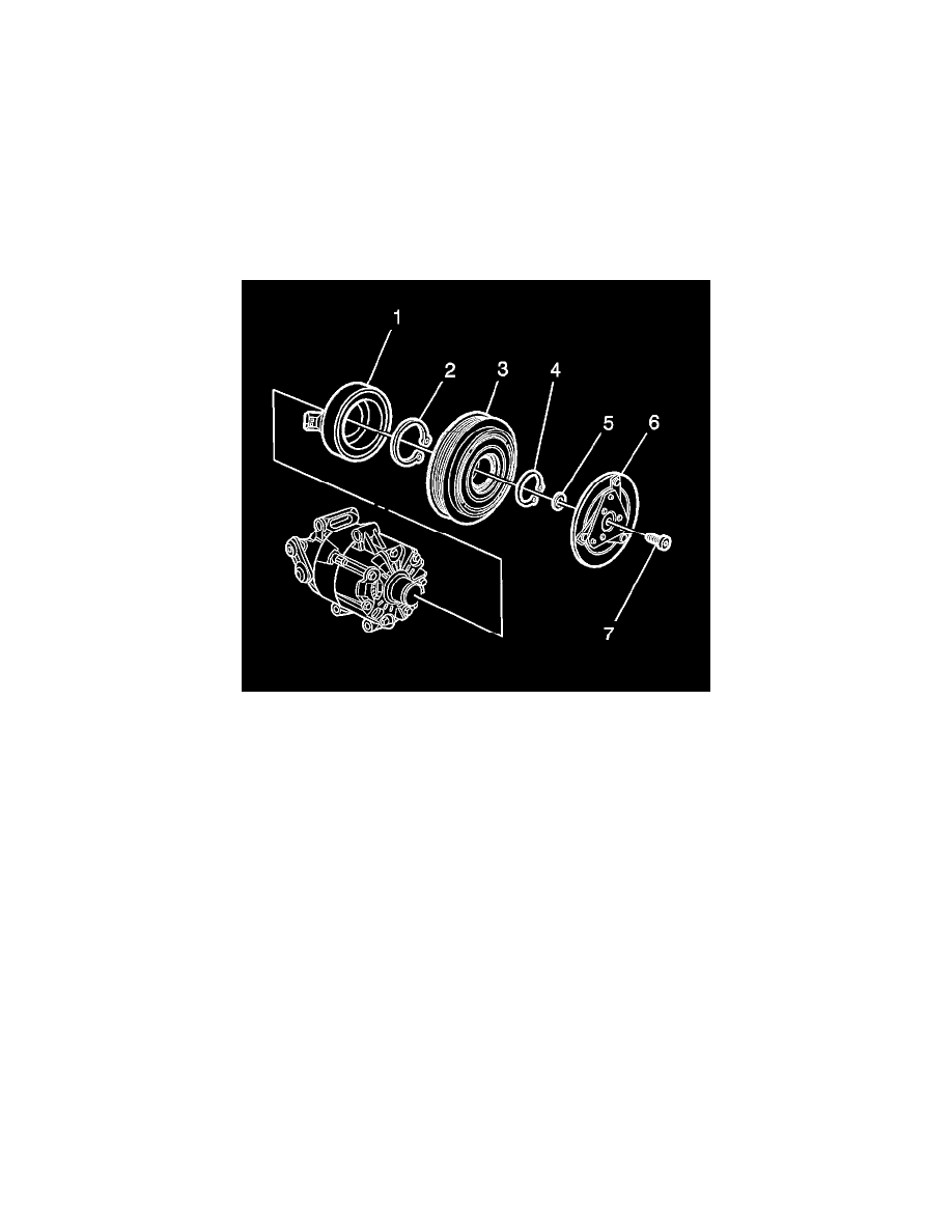
Important: There are air gap shims (5) between the clutch driver and the splined shaft.
4. Remove the clutch driver (6) from the splined shaft.
5. Remove and discard the pulley and bearing assembly retainer (4).
6. Remove the pulley and bearing assembly (3) from the A/C compressor.
7. Remove and discard the coil assembly retainer (2).
8. Remove the coil assembly (1) from the A/C compressor.
9. Carefully clean the splined shaft and the retainer grooves of any foreign debris.
10. Carefully clean the shaft threads of adhesive using a M6 x 1.0 tap.
Carefully blow out debris with compressed air.
Installation Procedure
1. Install the coil assembly (1) to the A/C compressor.
Important: Ensure that retainers are fully seated within their groove.
2. Install a new coil assembly retainer (2).
3. Install the pulley and bearing assembly (3) to the A/C compressor.
4. Install a new pulley and bearing assembly retainer (4).
Important: Using shims (5), ensure a 0.3-0.6 mm (0.011-0.024 in) air gap is between the clutch driver and pulley.
Use a light coat of clean PAG oil to hold the shims in place.
5. Install the clutch driver (6) to the splined shaft.
6. Measure the air gap between the clutch driver (6) and pulley (3). The air gap should be between 0.3-0.6 mm (0.011-0.024 in).
7. Ensure that the clutch driver (6) does not drag against the pulley (3) when the pulley is rotated.
Notice: Refer to Fastener Notice (See: Service Precautions/Vehicle Damage Warnings/Fastener Notice) .
8. Using J 37872 , install a new air conditioning clutch screw (7).
Tighten the screw to 10 N.m (89 lb in).