
Corvette V8-6.2L (2008)
Notice: To prevent possible electrostatic discharge damage to the BCM, do not touch the connector pins or soldered components on the circuit
board.
Notice: To prevent internal BCM damage, the ignition must be OFF when disconnecting or reconnecting power to BCM (for example, battery
cable, BCM connectors, BCM fuses, jumper cables, etc.).
Notice: The BCM electrical connectors are designed with tabs and slots that allow the connectors to only fit one way. The connectors do not
require excessive force if being installed correctly. Installing the connectors with the wrong mating half or upside down can cause damage to the
connector, the BCM, or other vehicle components or systems.
1. Turn OFF the ignition switch.
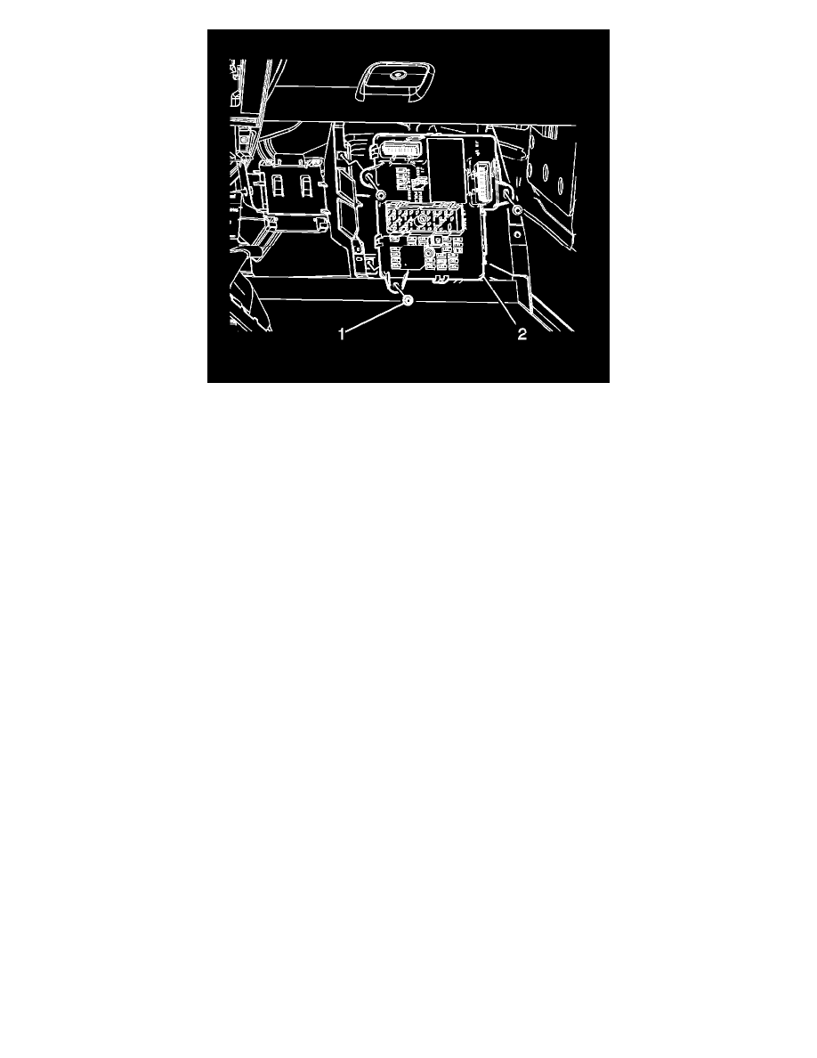
2. Connect the harness connectors to the BCM (2).
3. Position the BCM (2) to the multiuse bracket.
Notice: Refer to Fastener Notice (See: Service Precautions/Vehicle Damage Warnings/Fastener Notice) .
4. Install 3 retaining screws (1) to the BCM (2).
Tighten the screws to 2 N.m (18 lb in).
5. Install the kick-up panel. Refer to Front Floor Kick-Up Panel Replacement (See: Body and Frame/Interior Moulding / Trim/Trim Panel/Service
and Repair) .
6. If you are installing a new or replacement BCM, program the BCM to the current vehicle. Refer to Control Module References (See: Testing and
Inspection/Programming and Relearning) .