
Corvette V8-6.2L (2008)
Electronic Brake Control Module: Service and Repair
Electronic Brake Control Module Replacement
Removal Procedure
Notice: Always connect or disconnect the wiring harness connector from the EBCM/EBTCM with the ignition switch in the OFF position. Failure to
observe this precaution could result in damage to the EBCM/EBTCM.
Important:
*
The ignition switch must be placed in OFF mode ONLY, before disconnecting the negative battery cable during this procedure. If the
ignition switch is accidentally placed into ignition ON engine OFF mode, the control modules will be activated and disconnecting the
negative battery cable will cause various DTCs to be set. Refer to Keyless Entry System Description and Operation (See: Accessories and
Optional Equipment/Antitheft and Alarm Systems/Keyless Entry/Description and Operation) .
*
After the ignition switch is placed into OFF mode, a waiting period of 2 minutes must be observed to allow the high-speed LAN control
modules to deactivate before disconnecting or connecting the negative battery cable during this procedure. If the waiting period is not
observed, one or more of these control modules may still be active, this will cause various DTCs to be set.
1. Place the ignition switch into OFF mode . Do NOT place the ignition switch into ignition ON engine OFF mode.
2. Wait for a minimum of 2 minutes to allow the high-speed LAN control modules to deactivate.
3. Disconnect the negative battery cable. Refer to Battery Negative Cable Disconnection and Connection (6.0L) (See: Starting and
Charging/Battery/Battery Cable/Service and Repair)Battery Negative Cable Disconnection and Connection (7.0L) (See: Starting and
Charging/Battery/Battery Cable/Service and Repair) .
4. Thoroughly clean the electronic brake control module (EBCM) to brake pressure modulator valve (BPMV) area of any dirt or contaminants.
5. Raise and support the vehicle. Refer to Lifting and Jacking the Vehicle (See: Maintenance/Service Intervals) .
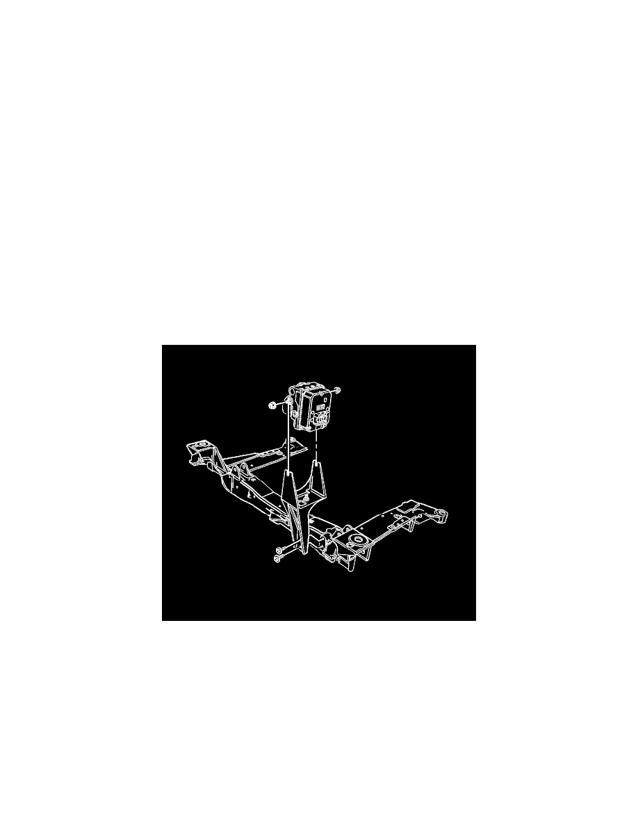
6. Remove the two BPMV bracket-to-crossmember mounting bolts to improve access to the EBCM and connector.
7. Support the ABS modulator assembly.
8. Disconnect the electrical connector from the brake fluid pressure sensor.