
Corvette V8-6.2L (2008)
4. Once the front 2 locks are unlocked, lift the front of the dress cover and pull it forward.
Important: Always use care when removing a terminal position assurance (TPA) in order to avoid damaging it.
5. Remove the TPA by inserting a small flat-blade tool into the small slot on the TPA and pushing down until the TPA releases. Gently pry the TPA
out of the connector.
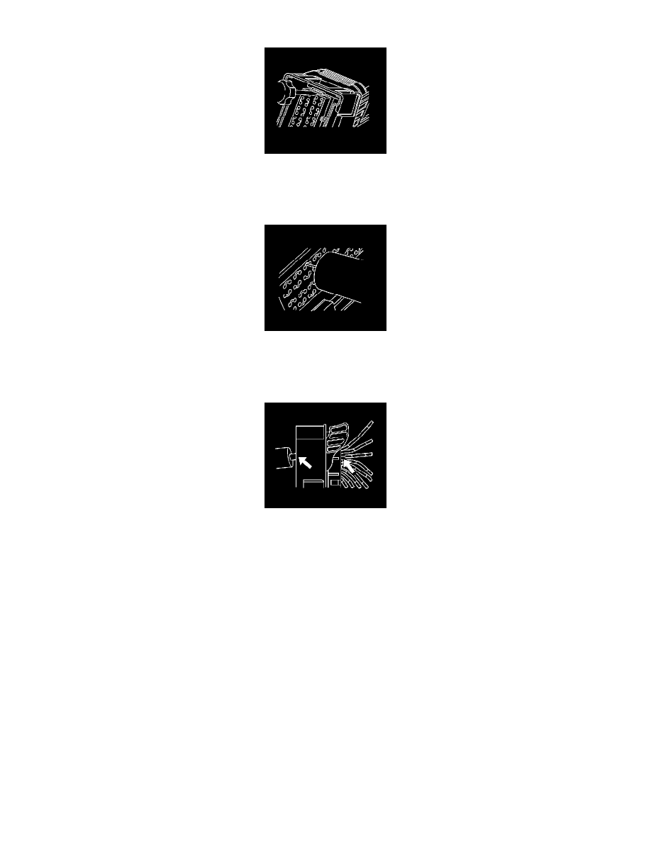
Important: Be careful not to angle or rock the J 38125-21 tool when inserting it into the connector or the tool may break.
6. Insert the J 38125-21 (GM P/N 15381651-2) tool into the round canal between the terminals cavities at the front of the connector. See the release
tool cross reference in the Reference Guide of the J-38125 to ensure that the correct release tool is used.
7. While holding the removal tool in place, gently pull the wire out of the back of the connector. Always remember never use force when pulling a
terminal out of a connector.
Repair Procedure
Follow the steps below in order to repair Micro 64 connector terminals.
The Micro 64 connectors have small terminals that are difficult to handle and hold when crimping. In order to aid the technician when crimping these
terminals, a new crimping tool was developed. The J 38125-64 (M jaw) was developed to crimp Micro 64 terminals. The J 38125-64 crimping tool has a
terminal holding block that will hold the terminal in place while the terminal is being crimped. The J 38125-64 crimping tool is also designed to crimp
both the wire and the insulation at the same time.
After the terminal is removed from the connector perform the following procedure in order to repair Micro 64 terminals.
Important: After cutting the damaged terminal from the wire, determine if the remaining wire is long enough to reach the connector without
putting a strain on the wire. If the wire is not long enough, splice a small length of the same gage wire to the existing wire, then crimp the new
terminal on the added wire.
1. Cut the wire as close to the damaged terminal as possible.
2. Strip 5 mm (3/16 in) of insulation from the wire.